

Have you ever wondered why cars slow down when you stop pressing the gas pedal? Or why cyclists lean forward to go faster? The answer is drag force. Simply put, drag in aerodynamics is the force that pushes against any object moving through air. Moreover, aerodynamic drag affects everything around us. From the air drag on your car to the resistance felt by airplanes, drag force is everywhere. In fact, understanding what is drag in aerodynamics helps engineers design better vehicles, save fuel, and improve performance.
Furthermore, this guide will explain drag in the simplest terms. We’ll explore different types of drag, learn the drag equation, and discover how to reduce aerodynamic drag. Additionally, you’ll understand why adverse pressure gradient causes drag and how CFD simulation helps predict drag force.
Most importantly, whether you’re a student, engineer, or just curious about aerodynamics drag, this article makes complex concepts easy to understand. So, let’s dive into the fascinating world of drag in aerodynamics!
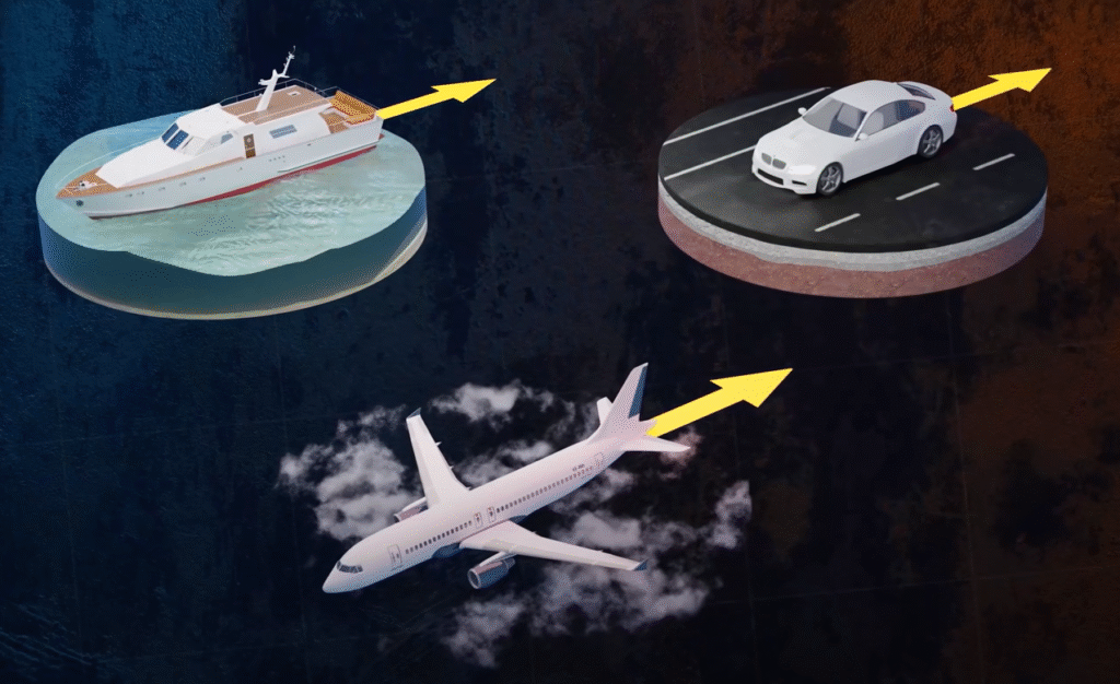
Figure 1: Drag force causes a strong resistance toward our vehicles during motion
What is Drag in Aerodynamics?
Let’s explain it very simply. Drag is the force that tries to slow down anything moving through air. When you walk against strong wind, you feel drag force pushing you back. That’s aerodynamic drag in action! Moreover, drag in aerodynamics happens for two main reasons. First, when objects move through air, they push air molecules away. This creates pressure drag. Second, air sticks to surfaces and creates friction drag. Together, these forces make aerodynamic drag. Think about a car driving on a highway. The faster it goes, the more air drag it faces. This is why cars use more fuel at high speeds. In fact, drag force increases with speed squared. This means if you double your speed, drag becomes four times stronger!! Look at Figure 2. If you consider the airflow that is coming from left to right, then Fd shows the drag force applied on the wing.
Additionally, aerodynamics drag affects all moving objects. Airplanes, cars, bicycles, and even runners face drag. Engineers spend years studying what is drag in aerodynamics to make vehicles more efficient. Simply put, less drag means less fuel and more speed.
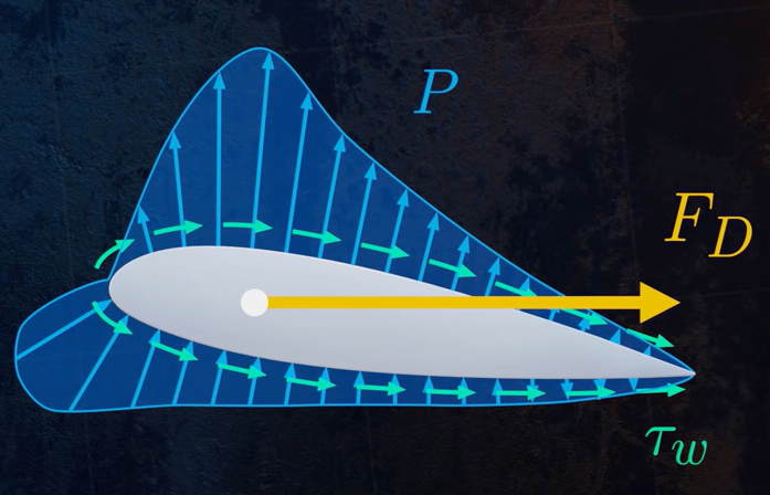
Figure 2: Schematic of drag force applying on an airfoil
Types of Drag in Aerodynamics
Understanding types of drag is essential for aerodynamics analysis. There are four primary types of drag in aerodynamics that affect objects moving through air. Each type of drag has different causes and characteristics.
1. Pressure Drag (Form Drag)
Pressure drag, also known as form drag, results from pressure differences around an object. When air flows around a body, it creates high pressure at the front and low pressure at the back. This pressure difference generates pressure drag. Moreover, form drag depends directly on the object’s shape and frontal area. Blunt bodies produce high pressure drag, while streamlined shapes minimize this type of drag. The adverse pressure gradient behind objects causes flow separation, which increases form drag significantly.
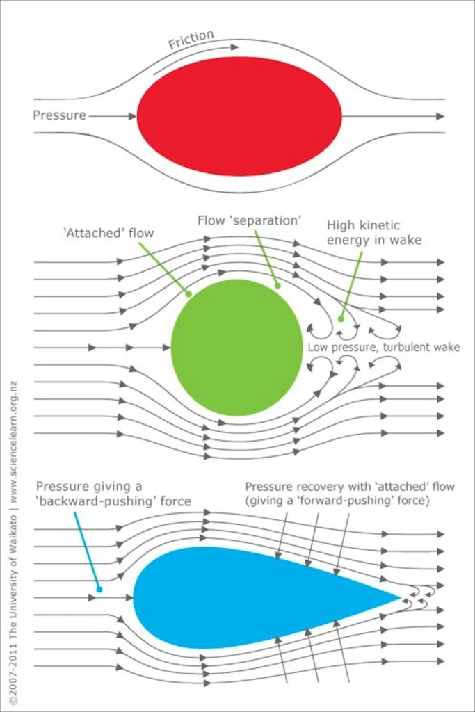
Figure 3: Object`s shape directly affects the pressure drag
2. Skin Friction Drag
Skin friction drag originates from viscous forces in the boundary layer. As air flows over a surface, molecular viscosity creates shear stress between fluid layers. This phenomenon produces friction drag. Furthermore, skin friction drag depends on surface roughness, wetted area, and Reynolds number. Smooth surfaces reduce viscous drag, while rough surfaces increase it. This type of drag is particularly important for large surface areas like aircraft fuselages.
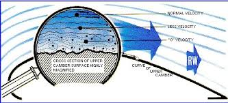
Figure 4: Skin friction drag due to surface roughness
3. Induced Drag
Induced drag is unique to lifting surfaces such as wings. When wings generate lift, they create wingtip vortices that alter the flow field. These vortices cause induced drag as an unavoidable consequence of lift production. Additionally, induced drag decreases with aspect ratio and increases with lift coefficient squared. High-efficiency wings minimize induced drag through optimal span loading.
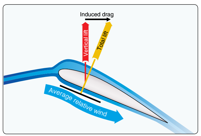
Figure 5: Induced drag as the side effect of lift generation
4. Wave Drag
Wave drag appears at transonic and supersonic speeds. When objects approach Mach 1, shock waves form and create wave drag. This type of drag results from energy loss across shock waves. Moreover, wave drag increases dramatically near the speed of sound, creating the “sound barrier” effect.
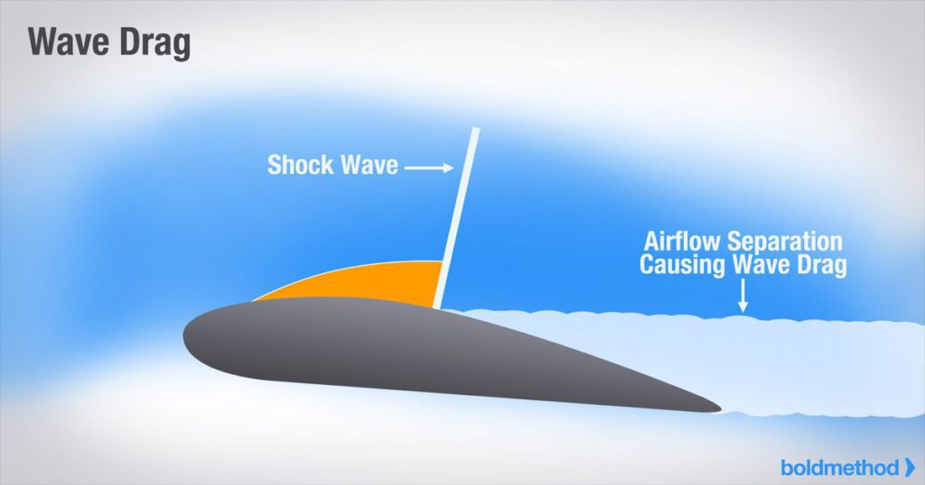
Figure 6: Wave drag as the consequences of exceeding transonic speeds – image taken from boldmethod website
Drag Coefficient – The Key to Understanding Drag
What makes some objects more aerodynamic than others? The answer is the drag coefficient. Simply put, the drag coefficient (or Cd) is a number that tells us how easily an object moves through air. Moreover, think of drag coefficient as a score for aerodynamics. A low Cd means less drag, while a high Cd means more drag. For example, a raindrop has a very low drag coefficient because of its streamlined shape. On the other hand, a parachute has a high Cd because it’s designed to catch air.
Common Drag Coefficient Values
Here are typical drag coefficient values for everyday objects:
| Object | Drag Coefficient (Cd) | Description |
|---|---|---|
| Streamlined body | 0.04 | Best aerodynamic shape |
| Airplane wing | 0.05 | Designed for low drag |
| Modern sports car | 0.25-0.30 | Optimized for speed |
| Regular car | 0.30-0.35 | Balance of style and aerodynamics |
| Sphere | 0.47 | Like a ball or raindrop |
| Bicycle rider | 0.9 | Upright position creates drag |
| Cylinder | 1.0 | Like a pipe in crossflow |
| Flat plate | 1.28 | Maximum drag perpendicular to flow |
| Parachute | 1.3-1.4 | Designed for high drag |
Furthermore, the drag coefficient changes with flow conditions. At different speeds and angles, the same object can have different Cd values. This is why wind tunnel testing is important for finding accurate drag coefficients. Engineers work hard to reduce drag coefficient in their designs. Even a small decrease in Cd can save lots of fuel. For instance, reducing a car’s drag coefficient from 0.30 to 0.25 improves fuel economy by about 5%. Most importantly, the drag coefficient helps us compare different shapes fairly. Since Cd is dimensionless, we can compare a tiny model in a wind tunnel to a full-size aircraft. This makes the drag coefficient essential for aerodynamic drag analysis.
Flow Separation and Adverse Pressure Gradient in Aerodynamics
What is Flow Separation in Aerodynamics?
Have you ever noticed the swirling air behind a moving truck? That’s flow separation in action. Simply put, flow separation happens when air stops following the surface of an object and creates swirls instead. When flow separation occurs, drag force increases dramatically. Flow separation is a key concept in aerodynamics. When air flows around an object, it normally sticks to the surface in what we call the boundary layer. However, under certain conditions, this air layer breaks away or “separates” from the surface. This creates a turbulent wake behind the object, leading to increased pressure drag.
Understanding the Adverse Pressure Gradient
The flow separation phenomenon is associated with an adverse pressure gradient.
The main cause of flow separation is something called an adverse pressure gradient. What does this mean? An adverse pressure gradient happens when air pressure increases in the direction of flow. This increasing pressure works against the flowing air, slowing it down. When an adverse pressure gradient becomes too strong, it actually pushes air backward near the surface. This backward flow causes the boundary layer to separate from the surface, creating flow separation. The point where this happens is called the separation point.

Figure 7. Velocity profile associated with separation on a circular cylinder in cross flow. From Incropera et al., Fundamentals of Heat and Mass Transfer, 7th edition, Wiley.

Figure 8. Boundary layer formation and separation on a circular cylinder in cross flow. From Incropera et al., Fundamentals of Heat and Mass Transfer, 7th edition, Wiley.
Since the momentum of the fluid in a turbulent boundary layer is greater than in a laminar boundary layer, it is reasonable to expect that transition to turbulence delays the occurrence of separation. For this reason, efforts are made to disturb the airflow over the surface of the object. One method is to increase surface roughness. For example, a golf ball has dimples on its surface that induce turbulent flow and delay separation. This modification reduces pressure drag and increases frictional drag, resulting in an overall reduction in drag.

Figure 9. The effect of turbulence on separation. From Incropera et al., Fundamentals of Heat and Mass Transfer, 7th edition, Wiley.
| Concept | Description | Effect on Drag |
|---|---|---|
| Flow Separation | Boundary layer detachment from surface | Greatly increases drag |
| Adverse Pressure Gradient | Pressure increases in flow direction | Causes flow separation |
| Separation Point | Where flow detaches from surface | Determines size of wake region |
| Wake Region | Turbulent area behind object | Creates low pressure, increasing drag |
Engineers design shapes to minimize adverse pressure gradients. Streamlined shapes like teardrops and airfoils delay flow separation by creating gentler pressure changes. Meanwhile, blunt objects like trucks and buildings experience early flow separation due to strong adverse pressure gradients.
Drag Force Formula and Equations
Understanding the drag equation is essential for calculating aerodynamic drag. The drag force formula helps engineers predict how much drag force an object will experience.
The Drag Force Formula
The fundamental drag equation calculates drag force using five key variables:
![\[ F_D=\frac{1}{2}C_D \rho U^2A \]](https://cfdland.com/wp-content/ql-cache/quicklatex.com-a060b3297cf244b907a6c7755371c08a_l3.png "Rendered by QuickLaTeX.com")
Let’s understand each part of this drag force formula in simple terms:
-
D (Drag Force): This is the total aerodynamic drag measured in Newtons or pounds. The drag force always opposes motion through air.
-
ρ (Air Density): Air density affects drag significantly. Cold air is denser than hot air, so drag force increases in cold weather. At sea level, air density is about 1.225 kg/m³.
-
V (Velocity): Speed has the biggest impact on drag. Since velocity is squared in the drag equation, doubling speed quadruples the drag force. This explains why aerodynamic drag becomes critical at high speeds.
-
Cd (Drag Coefficient): The drag coefficient represents how streamlined an object is. Lower Cd means less drag. For example, a sphere has Cd = 0.47, while a streamlined car has Cd = 0.25-0.35.
-
A (Reference Area): This is typically the frontal area for vehicles or wing area for aircraft. Larger areas create more drag force.
How to Calculate Drag Force
To use the drag force formula, simply multiply all values together. For instance, calculating aerodynamic drag on a car requires knowing its drag coefficient, frontal area, speed, and air density. Engineers use this drag equation to optimize designs and reduce drag.
The drag coefficient can be determined through experimental results or analytical solutions. It is also possible to calculate the drag coefficient using Computational Fluid Dynamics (CFD) simulations, although this typically requires validation against experimental data. One example of a drag coefficient obtained analytically is the Stokes drag, which applies to spherical objects floating in a fluid with a Reynolds number (Re) less than 1. For this situation:
![\[ A=\pi r^2 \]](https://cfdland.com/wp-content/ql-cache/quicklatex.com-32040d3717fe39beb22bcad34d0beaf1_l3.png "Rendered by QuickLaTeX.com")
![\[ C_D=\frac{24}{\mathrm{Re}} \]](https://cfdland.com/wp-content/ql-cache/quicklatex.com-c33a643b97998f62b82f3bb868fd6484_l3.png "Rendered by QuickLaTeX.com")
![\[ F_D=6\pi r \mu U \]](https://cfdland.com/wp-content/ql-cache/quicklatex.com-9a14260ae044d0ad882943ed0e140508_l3.png "Rendered by QuickLaTeX.com")
Where r is sphere radius and Re is Reynolds number. In many cases, the drag coefficient CD is determined using experimental results and is presented in figures, such as Figure 7, as a function of the Reynolds number.

Figure 10. Drag coefficients for a smooth circular cylinder in cross flow and for a sphere. Boundary layer separation angles are for a cylinder, from Incropera et al., Fundamentals of Heat and Mass Transfer, 7th edition, Wiley.
Factors Affecting Drag and Effective Reduction Techniques
What Influences Aerodynamic Drag?
Aerodynamic drag depends on several key factors. Understanding these factors affecting aerodynamic drag helps engineers design more efficient vehicles and structures.
Here are the main factors that influence aerodynamic drag:
| Factor | Effect on Drag | Example |
|---|---|---|
| Velocity | Drag increases with the square of velocity | Doubling speed creates four times more drag |
| Shape | Streamlined shapes reduce drag | Teardrop shape has 85% less drag than a sphere |
| Frontal Area | Larger areas create more drag | Reducing frontal area by 10% cuts drag by 10% |
| Surface Roughness | Smoother surfaces typically have less drag | Polished surfaces reduce skin friction drag |
| Air Density | Higher density increases drag | Aircraft experience less drag at high altitudes |
Moreover, Reynolds number affects how air flows around objects. At different Reynolds numbers, the same shape can have completely different drag characteristics.
Effective Drag Reduction Techniques
Engineers use many clever drag reduction methods to improve efficiency. Here are proven ways to reduce aerodynamic drag:
-
Streamlining – Reshaping objects to minimize flow separation. Car manufacturers spend millions to improve designs for better fuel economy.
-
Surface Modifications – Golf ball dimples actually reduce drag by creating a thin turbulent boundary layer. Similarly, riblets on swimsuits helped athletes break records.
-
Vortex Generators – Small fins on wings and cars control flow separation and reduce drag at specific speeds.
-
Active Flow Control – Using small jets or moving surfaces to influence airflow around objects.
At CFDLand, we’ve completed several advanced projects demonstrating aerodynamic drag reduction:
This project shows how adding a simple flap to a blunt body can significantly reduce drag by mean of ANSYS Fluent. The properly positioned flap changes the flow separation pattern and reduces the wake region.

Figure 11: Drag reduction on Ahmed Body by implementing a Flap CFD Simulation
Our advanced simulation shows how changing an airfoil’s shape using mesh morphing technology can optimize the lift-to-drag ratio. This technique helps design more efficient wings and hydrofoils. These projects demonstrate how small design changes can lead to big improvements in aerodynamic performance. Using advanced CFD simulation tools like ANSYS Fluent, engineers can test many designs quickly without building physical prototypes.
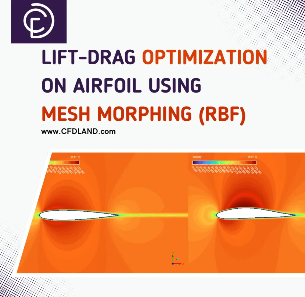
Figure 12: Lift-drag optimization using advanced Mesh Morphing tool of ANSYS Fluent
At CFDLAND, our experts perform your aerospace projects with high speed and accuracy, including drag force calculations using CFD simulation with ANSYS Fluent software. You can order your projects in the “ORDER PROJECT” section, and you will be surprised by the quality of our work. We suggest you take a look at our “CFDSHOP”, where we have many ready-made aerodynamic projects that you might find useful.
Conclusion – Understanding Drag Through CFD
Aerodynamic drag affects everything from cars and aircraft to buildings and sports equipment. The four main types of drag (pressure, skin friction, induced, and wave) work together to resist motion through air. Understanding the drag equation and drag coefficient helps engineers predict and manage these forces.
Today, CFD simulation (Computational Fluid Dynamics) has revolutionized aerodynamic analysis. Using CFD software like ANSYS Fluent, engineers can visualize airflow patterns that are invisible in physical testing. This technology helps:
- Predict drag forces accurately
- Identify flow separation points
- Test design changes quickly
- Optimize shapes for minimum drag
CFD modeling has become essential for aerodynamic development across industries. From reducing car drag coefficients to optimizing aircraft wings, numerical simulation provides insights that were once impossible to obtain.
For more advanced flow simulation techniques and optimization methods, explore our detailed tutorials and project examples at CFDSHOP.
Related Blogs:
Want to learn more about aerodynamics and fluid flow? Check out these related articles:
• What is Aerodynamic Lift? – Understand how lift works alongside drag in aerodynamics. The counterpart to drag force!
• Discrete Phase Model Drag Law – Explore different drag laws for particle simulations in multiphase flows.
• What is Reynolds Number? – Learn about this critical dimensionless number that determines flow behavior and drag characteristics.