As stated in the Discrete Phase Model Physical Models article, ANSYS Fluent predicts the trajectory of particles by integrating the force balance on the particle. This force balance is written in a Lagrangian reference frame and has an independent term shown by FD that represents drag force per unit particle mass.
Contents
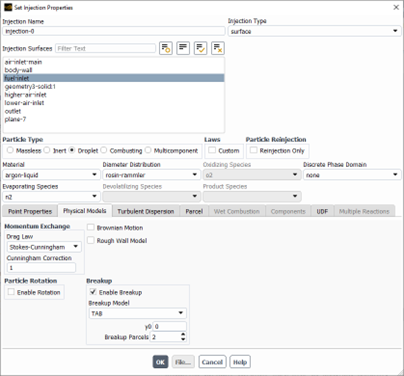
ToggleDiscrete Phase Model drag laws describe the forces exerted on discrete particles by the surrounding fluid, influencing particle trajectories and overall flow dynamics. ANSYS Fluent offers various drag law formulations, accessible from the following path (see Fig. 1):
Injection Window ==> Physical Models Tab
Understanding these drag laws and their appropriate application is essential for engineers who aim to optimize their DPM simulations.

Figure 1: Discrete Phase Model (DPM) drag laws in ANSYS Fluent
In some references, 14 draw laws are introduced for discrete phase model. However, there are 7 drag laws provided in ANSYS fluent for Discrete Phase Model. The rest of the drag laws are dedicated to the Dense Discrete Phase Model. This article concentrates on the theoretical and practical descriptions of DPM drag laws.
1) DPM-Spherical Drag Law
The Spherical drag law is the most commonly used drag model for the Discrete Phase Model (DPM) simulations. As its title suggests, it is designed for particles that are approximately smooth spherical in shape. Theoretically, the software calculates the drag coefficient taken from the following equation:
![]()
Where:
- CD represents the drag coefficient
- a1, a2, and a3 are constants
- Re represents the Reynolds number
It can be concluded that the drag coefficient completely depends on the Reynolds number. For better visualization, see Fig. 2. This plot illustrates a clear relationship between drag coefficient versus Reynolds number. The graph shows three distinct regions:
- A linear decrease from 10^-3 <Re< 10^2
- A more gradual decrease from 10^2<Re<10^4
- Re>10^4
The overall trend shows a decreasing relationship, with the drag coefficent values ranging from 10^5 to 10^-1.

Figure 2: Drag coefficient Vs. Reynolds number for Discrete Phase Model spherical drag law
2) DPM Non-Spherical Drag Law
In most cases, it is an idealistic view to consider all particle spheres. Realistically, the particles are mostly like distorted spheres. This approach is taken by using the Nonspherecial drag law in ANSYS Fluent. Avoiding the theoretical complex formulation, there is an important term inside the formulation that plays a critical role in calculations, known as shape factor(ϕ). Fig. 3 depicts the nonspherical drag law model in ANSYS Fluent. After selecting this model, the software asks for a definition of the shape factor. The shape factor is a dimensionless number that quantifies the deviation of a particle’s shape from a perfect sphere. φ ranges from 0 to 1, where 1 represents a perfect sphere.
![]()
Where:
- Cd,sphere is the drag coefficient for a sphere, calculated based on the particle Reynolds number
- ϕ is the shape factor

Figure 3: Nonspherical drag law in ANSYS Fluent
Tip: Complex shapes may be estimated through experiments or detailed particle analysis. However, these shape factor values can be used:
- Sphere: 1.0
- Cube: ~0.81
- Cylinder: ~0.70
Tip 2: ANSYS Fluent visualizes all the particles as spheres and does not distinguish them by shape factor.
Effect of shape factor on drag coefficient in different Reynolds
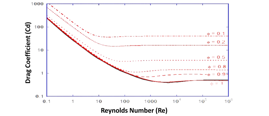
Fig. 4 is the graph illustrating the relationship between drag coefficient and Reynolds number for different shape factors. Reynolds number from 0.1 to 10^6, while the drag coefficient from 0.1 to 1000. Multiple curves are plotted, each corresponding to a different shape factor ranging from 0.1 to 1. All curves show a general decreasing trend as the Reynolds number increases, with the drag coefficient dropping at lower Reynolds numbers and leveling off at higher Reynolds numbers.
The curves for higher shape factors (φ = 0.8, 0.9, 1) closely overlap, especially at lower Reynolds numbers, while the curves for lower volume fractions (φ = 0.1, 0.2, 0.5) remain distinctly separated throughout the Reynolds number range.

Figure 4: Drag coefficient Verses Reynolds Number for nonspherical drag law
3) DPM Stokes-Cunningham Drag Law
This model modifies the standard Stokes drag law to account for non-continuum effects. According to fluid mechanics fundamentals, it becomes significant for particles with small diameters, in sub-micron scale. In other words, when the particle size approaches the mean free path of the fluid molecules.
The Stokes-Cunningham drag formulation is not our concern, but Fluent asks for the Cunningham correction factor after the selection of the Stokes-Cunningham drag law in the DPM panel (see Fig. 5). Here is the Cunningham factor formulation:
![]()
where:
- λ is the mean free path of the fluid,
- dp is the particle diameter,
- A1, A2, and A3 are constants.
The values of the constants A1, A2, and A3 can vary depending on the conditions and the specific fluid, but a commonly used set of values for air at standard conditions is:
A1=1.257 , A2=0.4 , A3=1.1
So, the formulation simplify to this form:
![]()
For example, the mean free path of air at standard atmospheric pressure and temperature (20°C) is approximately 0.066 µm. let’s say we have a particle with a diameter of 0.1 µm. Given the λ=0.066 µm ,dp=0.1 µm: Cc≈2.889.

Figure 5: Stokes-cunningham drag law panel in ANSYS Fluent
4) DPM High-Mach-Number Drag Law
The High-Mach-Number Drag Law in ANSYS Fluent is specifically designed to handle the drag force calculations on particles moving at high velocities, particularly when:
- Mach Number > 0.4
- Particle Reynolds > 20
Tip: Particle Reynolds number is computed using the following equation:
![]()
Where:
- ρf is the fluid density (kg/m³).
- u is the relative velocity between the particle and the fluid (m/s).
- dp is the diameter of the particle (m).
- μ is the dynamic viscosity of the fluid (Pa·s or kg/(m·s)).
5) DPM Dynamic Drag Law
Initially, the dynamic drag law is only accessible when the droplet Break-up model is enabled. This model is applicable in almost any circumstance because, naturally, the droplets don`t remain spherical after injection. Nevertheless, the drag coefficient drastically increases as the droplets move through the air, especially when the Weber number is large.
Drag coefficient of a distorted spherical droplet is always higher compared to the drag exerted on a sphere based on the following equation:
![]()
where y is the droplet distortion.
Y=0 ==> No distortion (sphere)
Y=1 ==> Maximum distortion (disk)

Figure 6: Dynamic drag law in DPM – Droplet distortion after spray
6-7) DPM Ishii-Zuber & Grace Drag Laws
Ishii-zuber and Grace drag laws are very alike. They are also called Bubbly flow drag laws. These models are well-suited for predicting the drag force in bubbly flows where the liquid is the continuous phase and the gas forms dispersed bubbles. However, apart from the basic formulation, each has its own application:
- Ishii-zuber is the best option in cases where the gas phase is dispersed in the form of bubbles within a liquid. Common applications include boiling flows, bubble columns, and other gas-liquid reactors.
- The Grace drag model is an ideal choice for granular flows, such as fluidized beds, where particle concentration is high and interactions between particles is expected. It is also useful in sedimentation processes and other applications involving dense suspensions of solid particles.
You can get access to DPM CFD
Read more:

