

Computational Fluid Dynamics (CFD) has become an essential tool for optimizing pump performance across various industries. By leveraging CFD pump simulations in ANSYS Fluent, engineers can analyze and enhance the performance of different pump types, including centrifugal pumps, gear pumps, axial flow pumps, reciprocating pumps, and screw pumps. Since centrifugal pumps are the most widely used, this blog explores the significance of CFD in pump analysis, with a particular focus on centrifugal pump simulations using ANSYS Fluent. Centrifugal pump CFD analysis plays a crucial role in optimizing impeller design, reducing energy losses, and preventing cavitation. When setting up your own centrifugal pump simulations, carefully consider the mesh requirements and boundary condition specifications discussed above. If your project demands advanced expertise or you’re facing challenging pump configurations, our team at CFDland offers specialized Turbomachinery CFD Simulation services to help you achieve accurate, reliable results efficiently.
The Classification of Pumps: Dynamic vs. Positive Displacement Pumps
Pumps are generally classified into two main types: Dynamic Pumps and Positive Displacement Pumps (Fig.1). A dynamic pump moves fluid by imparting kinetic energy through a spinning impeller, making it ideal for high flow rates and low-viscosity liquids. It relies on direct mechanical methods, such as a propeller or impeller, to generate fluid motion. In contrast, a positive displacement pump moves a fixed volume of fluid by trapping it within a chamber and forcing it out, making it suitable for high-viscosity fluids and applications requiring precise flow control. These pumps achieve flow using pressure mechanisms like air or water force, including bellows-style systems.
![Figure 1- Positive Displacement Pumps vs. Dynamic Pumps [1]](https://cfdland.com/wp-content/uploads/2024/09/12.jpg)
Figure 1- Positive Displacement Pumps vs. Dynamic Pumps [1]
Fig. 2 illustrates the overall categorization of pumps. As centrifugal pumps are the most commonly pump which is used in industry, this blog highlights the importance of CFD in pump analysis, emphasizing centrifugal pump simulations in ANSYS Fluent.
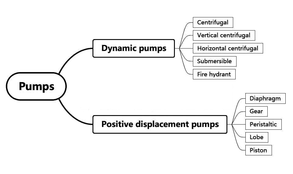
Figure 2- The general classification of pumps
What is a Centrifugal Pump?
In this pump model, rotational kinetic energy is converted to hydrodynamic energy. Figure below shows a schematic cutaway of a centrifugal pump. This pump has 4 main parts: suction pipe, discharge pipe, impeller and casing. The flow enters the pump from the suction pipe (duct 1 in the figure) and the flow leaves the pump with a higher pressure from the discharge pipe (duct 2 in the figure). The rotating member of the pump, Impeller, increases fluid pressure. The flow from the suction pipe is transferred vertically to the center of the impeller and by going to the outer radii of the impeller, its velocity decreases and its pressure increases until it finally exits the Discharge Pipe. Usually, the impeller is driven by an electric motor. Centrifugal pumps are a type of turbomachine.
The advantages of this pump model include its simple design and operation, high efficiency for a wide range of flow rates and pressures, and the need for relatively low maintenance. This pump model is used in water and sewage systems, HVAC systems, oil and petrochemical industries, and food industries.
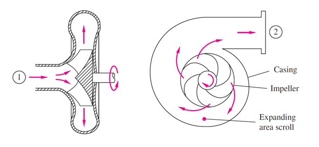
Figure 3: Cutaway schematic of a typical centrifugal pump. Adopted from “Fluid Mechanics” by Frank M. White
Key Components of Centrifugal Pump
The following Figure is an exploded view of parts of centrifugal pumps. This diagram is used to illustrate the various components of the pump and how they fit together. Each labeled part corresponds to a specific component of the pump, allowing for a clearer understanding of its assembly and function.
![Figure 3- Main components of a Centrifugal Pump[2]](https://cfdland.com/wp-content/uploads/2024/09/14.jpg)
Figure 4- Main components of a Centrifugal Pump[2]
Working principle of Centrifugal Pump
Centrifugal pumps operate based on the principle of centrifugal force. When the impeller rotates, it imparts velocity to the fluid, which is then converted to pressure as the fluid exits the pump. The key steps in the operation of a centrifugal pump are as follows (see Fig.4):
- Fluid Entry: The fluid enters the pump through the inlet (or suction) port, typically located at the center of the impeller.
- Impeller Rotation: The impeller, which consists of blades, rotates at high speed, creating a low-pressure area at the center that draws fluid into the pump.
- Fluid Acceleration: As the fluid passes through the impeller blades, it gains kinetic energy and is accelerated outward due to centrifugal force.
- Pressure Conversion: The high-velocity fluid then enters the volute or diffuser, where its velocity decreases, and the kinetic energy is converted into pressure energy, allowing the fluid to flow out of the discharge port.
![Figure 4- Centrifugal Pump: how it works[3]](https://cfdland.com/wp-content/uploads/2024/09/15.jpg)
Figure 5- Centrifugal Pump: how it works[3]
Applications of CFD in Centrifugal Pumps
There are various analytical and experimental methods to study pumps. In this method, the domain of fluid movement is discretized and for each cell, discretized unit, the equations governing the fluid flow are solved by the computer. Each method has its strengths and weaknesses. Analytical methods are simple and fast, but they explain the details of the pump’s performance with little accuracy, and many idealizations and assumptions are used in their calculations, which cause errors in the results. Experimental tests give accurate results but are expensive and it is very difficult to record the results inside the pump in this way. With advancements in centrifugal pump CFD, engineers can simulate and evaluate various pump behaviors, improving efficiency, reducing energy losses, and preventing operational failures.
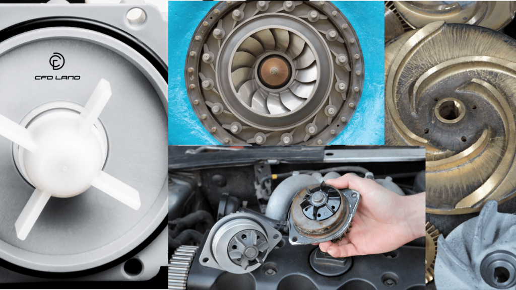
Figure 6: The shape of the impeller vanes can be different depending on the pump application and the fluid for which it is designed
- Performance Prediction and Optimization
Pump CFD analysis helps predict head-capacity curves, pressure distributions, and efficiency losses. Using centrifugal pump simulation using Fluent, engineers can optimize impeller and volute designs to reduce energy consumption and improve hydraulic efficiency. Design and CFD analysis of centrifugal pump ensures optimal blade angles and volute shapes, enhancing flow uniformity. Design and analysis of centrifugal pump impeller using ANSYS Fluent helps simulate impeller performance, reducing turbulence and improving efficiency (Fig.7).
![igure 5- Comparison of external characteristics of the prototype pump and optimized pump[4]](https://cfdland.com/wp-content/uploads/2024/09/7.jpg)
Figure 7- Comparison of external characteristics of the prototype pump and optimized pump[4]
Cavitation Analysis and Prevention
CFD analysis of cavitation in flow through a Gerotor pump and the prediction of erosion zones due to cavitation allows engineers to identify cavitation-prone areas (Fig.6). Additionally, CFD analysis of two-phase cavitating flow in a centrifugal pump with an inducer helps minimize cavitation effects, improving pump durability.
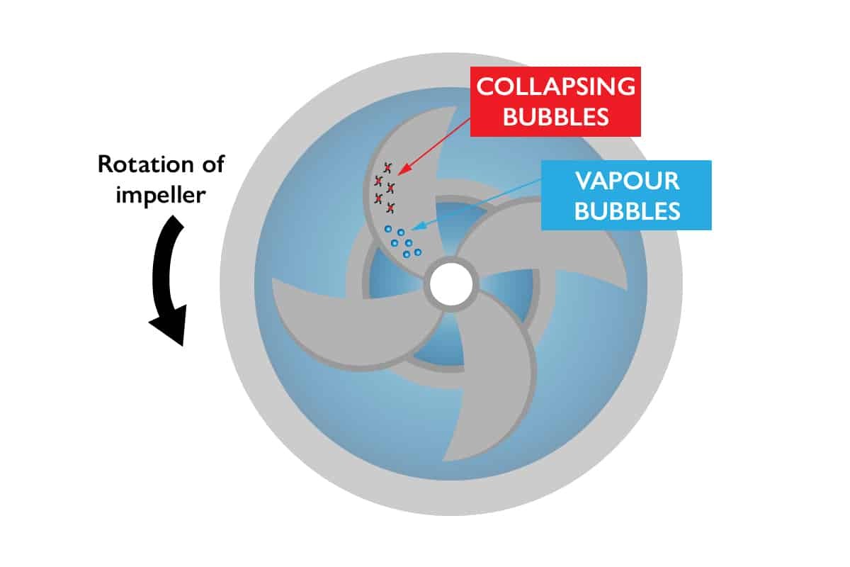
Figure 8- Pump cavitation phenomenon
Off-Design and Transient Flow Analysis
Pumps operate under varying conditions, making CFD centrifugal pump simulations crucial for identifying flow instabilities. Pump CFD analysis using techniques like Moving Reference Frame (MRF) and Sliding Mesh ensures stability and efficiency across different flow rates. MRF is used in CFD simulations, where separate static and rotating zones are present (Fig.9).
![Figure 7- Centrifugal Pump CFD Simulation with MRF[4]](https://cfdland.com/wp-content/uploads/2024/09/89.png)
Figure 9- Centrifugal Pump CFD Simulation with MRF[4]
Structural and Axial Thrust Analysis
Excessive axial thrust in centrifugal pumps can cause mechanical failures and increased wear. CFD analysis of pump helps identify pressure imbalances, enabling thrust reduction strategies such as balancing holes and optimized impeller designs (Fig.8). Additionally, Centrifugal Pump Design Optimization with CFD integrates fluid-structure interaction (FSI) to evaluate impeller stress and deformation, ensuring durability and improved performance in high-load applications (Fig.9). Boost your CFD skills with our Centrifugal Pump Impeller FSI Simulation training in ANSYS Fluent.
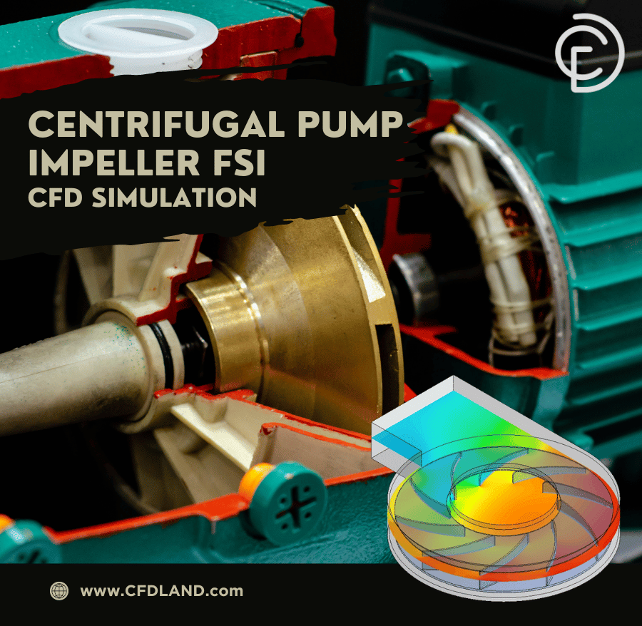
Figure 10: Centrifugal Pump Impeller FSI CFD Simulation, ANSYS Fluent Training
Non-Newtonian and Multiphase Flow Analysis
Numerical analysis of centrifugal pumps with ANSYS Fluent software is essential for handling complex fluids like slurries and crude oil. CFD pump simulations aid industries in oil & gas, mining, and food processing by predicting flow behavior in non-Newtonian and multiphase systems. Get expert training in Centrifugal Blood Pump CFD Simulation with ANSYS Fluent. Learn to simulate flow behavior in non-Newtonian and multiphase systems for accurate blood pump modeling (Fig.11).

Figure 11: Centrifugal blood pump CFD simulation. This project is just one of the simulations of centrifugal pumps by ANSYS Fluent, carried out by CFDLAND experts.
Thermal Analysis in Centrifugal Pumps
Heat generation inside a centrifugal pump occurs due to factors such as fluid friction, mechanical losses, and bearing heat dissipation. Effective heat transfer is crucial to prevent overheating, material degradation, and efficiency loss. CFD analysis of pump enables engineers to identify heat generation points, analyze temperature distribution, and optimize cooling mechanisms. By using CFD pump simulations, it is possible to evaluate different heat dissipation strategies, such as improving casing ventilation, optimizing lubricant flow, and enhancing thermal conductivity of components. Centrifugal pump CFD analysis provides valuable insights into how heat moves within the system, ensuring reliable operation and extended pump lifespan. Enhance your CFD skills with External Gear Pump CFD Simulation using Dynamic Mesh in ANSYS Fluent. Learn to simulate gear pump performance and optimize designs with dynamic mesh techniques. Buy now to advance your expertise!
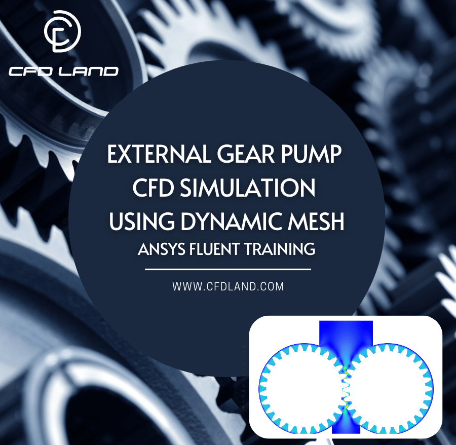
Figure 12: External Gear Pump CFD Simulation Using Dynamic Mesh – ANSYS Fluent Training
Numerical Formulation and Efficiency Calculation of a Centrifugal Pump in Fluent
In the analysis of steady-state incompressible flows, the conservation equations can be resolved using either the average Reynolds values or a time-averaging approach. However, the predominant method for modeling turbulent flows is the time-averaging technique.
Governing Equations
For the case of incompressible flows, the general forms of the governing equations could be expressed as relations (1)–(5). As we have a rotating control volume, these equations employ the relative motion, therefore the relative velocity of fluid W.
Since the pumped fluid is incompressible and the flow is in a steady state, the continuity equation has the following form:

The equation of conservation of momentum is expressed as Equation 2. Where ρ is the density of fluid, P is pressure, SM, the source term, and τ, the shear stress tensor.

For flows in a rotating frame of reference, rotating at a constant angular velocity ω, additional sources of momentum are required to account for the effects of the Coriolis force and the centrifugal force, written as Equations 3 and 4 respectively:


So that, the additional sources of momentum is written as Equation 5:

Where r is the location vector.
The Finite Volume Method (FVM) is widely used in centrifugal pump CFD analysis, ensuring mass, momentum, and energy conservation. Unlike other methods, FVM solves conservation equations within control volumes, making it ideal for pump CFD analysis. ANSYS Fluent enables precise centrifugal pump simulation using Fluent, dividing the domain into control volumes for accurate calculation of a centrifugal pump in Fluent. This approach enhances pump efficiency formulas, optimizing pump CFD and improving overall CFD analysis of pumps.


Where stands for the inlet pressure, Y and stand for the specifically unsolidified mass and charge velocity, respectively, and Q is charge flow rate where stands for the inlet pressure and stands for the specifically unsolidified mass and charge velocity, respectively.
ANSYS Fluent Tutorial: Simulation of centrifugal pump
Creating a simulation of a centrifugal pump using ANSYS Fluent involves several steps, from preprocessing to post-processing. Here’s a detailed guide for setting up and running this type of simulation.
Geometry Creation
You can create the geometry using ANSYS DesignModeler or another CAD software such as SOLIDWORKS (Fig.13). Typically, a centrifugal pump consists of components such as the impeller, volute, and suction and discharge pipes. Ensure the geometry includes a fluid domain for the flow and a solid domain for the pump parts.
![Figure 12- Centrifugal pump with impeller design using SOLIDWORKS software[6]](https://cfdland.com/wp-content/uploads/2024/09/9.jpg)
Figure 13- Centrifugal pump with impeller design using SOLIDWORKS software[6]
Meshing the Geometry
You can ANSYS Meshing or other software to discretize the geometry (Fig.14). Choose an appropriate mesh type (structured, unstructured, or hybrid) based on the complexity of your geometry. Mesh refinement around the blade surfaces of the impeller and regions with high gradients, like the volute and inlet/outlet, will improve solution accuracy. Boundary layer refinement is also important, especially near solid walls like the pump casing and impeller blades.
![Figure 13- Computation domain and meshes of centrifugal pump. (a) Whole passage, (b) mesh of impeller, (c) mesh of tongue region[7]](https://cfdland.com/wp-content/uploads/2024/09/10.jpg)
Figure 14- Computation domain and meshes of centrifugal pump. (a) Whole passage, (b) mesh of impeller, (c) mesh of tongue region[7]
Setting up the Simulation in ANSYS Fluent
The Fig.14 illustrates a workflow diagram, representing the key steps in Simulation of centrifugal pump in ANSYS Fluent. The steps include: Importing the Mesh, Defining Materials, Defining Boundary Conditions, Turbulence Model Selection, and Solver Settings.
Centrifugal Pump Efficiency Calculation
Overall, statistical analyses were conducted through simulations using ANSYS tools. The pump efficiency (η) in relation to NPSH was identified as a key objective function for real-time optimization of the selected pumps. The efficiency of an ideal centrifugal pump is outlined as follows.
Another method is CFD simulation. This method requires more knowledge than analytical methods. There is also a need to validate CFD simulation results with experimental results. The strength of this method is the detailed description of pump performance at every point inside the pump. In the following, we will review the CFD analysis of centrifugal pump.
- Pump Design and Optimization: Fluid velocity and pressure are well calculated by CFD simulation at any point of the pump domain. In this way, it is determined which parts of the pump are not working properly. Is the impeller suitable? Is the length of the impeller suitable? Is the speed of the impeller suitable for producing the desired pressure? Does part of the fluid pressure inside the pump decrease for various reasons? Such questions are answered by CFD simulation.
- Cavitation Assessment: If the fluid pressure in some points of the pump is less than the fluid vapor pressure, then the fluid vaporizes and bubbles are formed in the flow. When these bubbles collide with the impeller, they scratch its surface and damage its blades. This phenomenon can be seen in experimental tests from the damaged shape of the impeller, but the origin and point of bubble formation can be found by CFD simulation.
- Thermal Analysis: Heat is generated inside the pump for various reasons, and it is very important to transfer this heat to the environment. Investigating and finding heat generation points and finding the way of heat transfer is possible with CFD simulations.
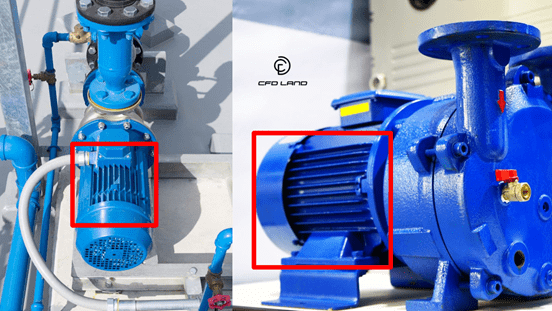
The parts inside the red rectangles are the vanes that are used to increase the heat transfer between the pump body and the ambient air.
Centrifugal Pump CFD Simulations by ANSYS Fluent
ANSYS Fluent is the right software for CFD centrifugal pump simulations. We will examine some of the features and capabilities of this software which is suitable for simulation in this field.
- Turbulent flows: Inside centrifugal pumps, there is usually a turbulent flow, and it is very important to accurately simulate this flow regime. ANSYS Fluent offers wide possibilities in this field, including all kinds of turbulence simulation models and the possibility of setting their details. In some cases, eddies may form in the fluid flow that disrupt the fluid flow, so that the new flow does not enter and exit the vortex, and the vortex occupies a part of the domain inside the pump, which makes the passage of the fluid flow smaller. This problem can be studied with the help of CFD simulations of turbulent flow with ANSYS Fluent.
- Fluid-Structure Interaction: In centrifugal pumps, sometimes it is necessary to check and analyze the stress. The load that enters the impeller shaft is asymmetric, which causes its deflection to change. Also, in various cases, there may be vibrations in the pump that cause unpleasant noise and even break the pump bases. Such issues can be simulated in ANSYS. With ANSYS Fluent, the fluid flow is simulated and the pressure distribution at different points of the pump is obtained, and with this data, the stress analysis in the pump structure is performed with the help of ANSYS Mechanical. See “What is Fluid-Structure Interaction?” for more information.
- Multiphase flows: In many applications of centrifugal pumps, the flow is multiphase, such as sewage flow. Flow contents may settle in the pump and block the passage. The design of the pump must be in a special way for each multiphase flow to create the appropriate pressure in the fluid. Simulation of multiphase flow with ANSYS Fluent is possible with various methods and features. See “Using ANSYS Fluent for Multiphase Flow Simulations: Techniques and Tips” for more information.
Click to access the Multiphas CFD
Calculation of Pump Performance Curves by ANSYS Fluent
Pump Performance Curves will be given to you at the time of purchase for each pump. As in the figure below, in this curve it is shown that the pump with the size of the impeller you want produces what head at each flow rate. Head is the unit of pressure based on the weight of the fluid column. In addition, the required power of the motor pump and its efficiency are drawn on such shapes. You may also have net positive-suction head (NPSH) as shown in the figure below. This parameter represents the minimum fluid pressure before entering the pump to prevent fluid vaporization and cavitation.
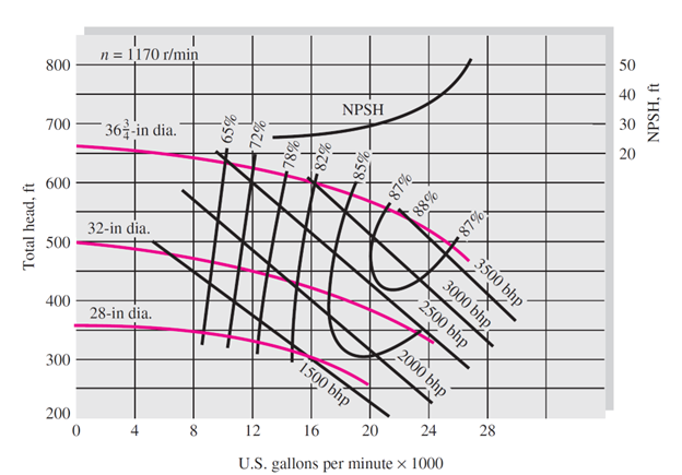
Measured-performance curves for a model of a centrifugal water pump with a basic casing with three impeller sizes. Adopted from “Fluid Mechanics” by Frank M. White
The following equation is used to calculate the head produced by the pump in ANSYS Fluent:
![\[ H=\frac{\Delta P}{\rho g} \]](https://cfdland.com/wp-content/ql-cache/quicklatex.com-fb2a31a1167d4551d75637b64cc5d28f_l3.png "Rendered by QuickLaTeX.com")
ΔP is the pressure difference before and after the pump [Pa], ρ is the fluid density [kg/m3], g is the acceleration due to gravity [m/s2], and H represents the pump head [m]. This equation is usually defined in the form of an expression in Fluent. In the simulation, H is recorded in each iteration until its value converges.
Conclusion
In this study, the significance of centrifugal pump CFD analysis using ANSYS Fluent is highlighted as a crucial methodology for optimizing pump performance across various applications. By utilizing CFD pump simulations, engineers can effectively analyze and enhance the efficiency of different pump types, particularly centrifugal pumps, through improved impeller design, reduced energy losses, and prevention of cavitation. The tutorial outlines essential steps, including geometry creation, meshing, and simulation setup, emphasizing the importance of CFD analysis of centrifugal pumps in predicting performance, optimizing designs, and ensuring reliability. With the ability to conduct pump CFD analysis and evaluate critical parameters such as pump efficiency formula, this study demonstrates how CFD serves as an indispensable tool in modern pump engineering, ultimately leading to enhanced operational efficiency and durability in various industrial applications.
CFD simulation of centrifugal pumps is a specialized work and requires a lot of knowledge and experience. CFDLAND specialists are experts in this field and have done many projects, some of which you can see in turbomachinery cfd SHOP. Ease your work and order CFD analysis and simulation projects of centrifugal pumps with ANSYS Fluent to CFDLAND with confidence in our abilities.
FAQs
- What is the role of Computational Fluid Dynamics (CFD) in pump analysis?
CFD is essential for optimizing pump performance by allowing engineers to analyze and enhance the efficiency of various pump types, including centrifugal pumps.
- What are the main types of pumps?
Pumps are classified into two main types: Dynamic Pumps, which use kinetic energy to move fluids, and Positive Displacement Pumps, which move a fixed volume of fluid by trapping it in a chamber.
- How does a centrifugal pump work?
A centrifugal pump works by converting rotational energy from the impeller into kinetic energy, accelerating the fluid and converting that energy into pressure as the fluid exits the pump.
- What applications benefit from CFD analysis of centrifugal pumps?
CFD analysis is beneficial in applications such as performance prediction, cavitation analysis, off-design flow analysis, structural analysis, and thermal management in centrifugal pumps.
- What turbulence models are commonly used in centrifugal pump simulations?
The k-ε and k-ω turbulence models are commonly used, with k-ω SST preferred for simulations that involve boundary layers and flow separation.
- How is pump efficiency calculated in CFD analysis?
Pump efficiency is calculated based on the inlet and outlet pressures, flow rates, and the specific energy losses within the pump, often using the pump efficiency formula.
Related Articles
Expand your knowledge of centrifugal pump CFD simulation with these related resources:
-
Cavitation: Causes, Effects, Solutions & CFD Simulation – Learn how to identify and mitigate pump cavitation phenomena through advanced simulation techniques. Understanding this critical issue is essential for designing reliable and efficient centrifugal pumps with extended operational lifespans.
-
What is Static Pressure? – Master the fundamental fluid dynamics concept that drives pump performance analysis. Static pressure distribution throughout a centrifugal pump provides crucial insights into energy transfer efficiency and potential design improvements.
-
Comprehensive Guide on Volume of Fluid (VOF) Model in Multiphase CFD Simulation – Discover how the VOF approach enables accurate modeling of free-surface flows and multiple fluid interactions within pump systems, particularly for self-priming applications and partially-filled operating conditions.
-
Different Regimes of Two-Phase Flow – Understand how various multiphase flow patterns affect centrifugal pump performance when handling gas-liquid mixtures, emulsions, or slurries in industrial applications.
-
CFD Applications – Explore how pump simulation techniques fit within the broader landscape of computational fluid dynamics applications across industries from HVAC to aerospace.
References
[1] https://www.linquip.com/blog/types-of-positive-displacement-pump/, ed.
[2] https://www.mppumps.com/, ed.
[3] https://www.gibbonsgroup.co.uk/media/blog/5-golden-rules-of-centrifugal-pump-maintenance/, ed.
[4] Y. Wang, L. Zhou, M. Han, and L. Shen, “Performance Prediction of an Optimized Centrifugal Pump with High Efficiency,” Fluid Dynamics & Materials Processing, vol. 19, no. 9, 2023.
[5] Q. He, X. Huang, M. Yang, H. Yang, H. Bi, and Z. Wang, “Fluid–Structure coupling analysis of the stationary structures of a prototype pump turbine during load rejection,” Energies, vol. 15, no. 10, p. 3764, 2022.
[6] J. Sossa-Echeverria and F. Taghipour, “Computational simulation of mixing flow of shear thinning non-Newtonian fluids with various impellers in a stirred tank,” Chemical Engineering and Processing: Process Intensification, vol. 93, pp. 66-78, 2015.
[7] T. Lei, Z. B. Shan, C. S. Liang, W. Y. Chuan, and W. B. Bin, “Numerical simulation of unsteady cavitation flow in a centrifugal pump at off-design conditions,” Proceedings of the Institution of Mechanical Engineers, Part C: Journal of mechanical engineering science, vol. 228, no. 11, pp. 1994-2006, 2014.