


A Centrifugal Pump Impeller FSI CFD simulation helps us design stronger and more reliable pumps. Centrifugal pumps are very important machines used everywhere, from moving water in our homes to handling oil in big factories. The main part of a pump is the impeller, which is like a spinning wheel with blades, as seen in Figure 1. When this impeller spins very fast in water, the water pushes hard against its blades. This pushing force can cause the impeller to bend or twist a little bit. This bending is called “structural deformation.”
Understanding how the water pushes and how the impeller bends is called Fluid-Structure Interaction (FSI). Our study uses a special type called “one-way FSI.” This means we first use ANSYS Fluent to calculate all the forces from the water on the impeller. Then, we send these force numbers to ANSYS Structural to see exactly how much the steel impeller bends. This method works well when the bending is small and does not change how the water flows too much. By doing this Centrifugal Pump FSI Fluent analysis, engineers can make better pumps that last longer, work more efficiently, and make less noise and vibration. This study is based on important engineering principles.
- Reference [1]: Babayigit, Osman, et al. “Numerical identification of blade exit angle effect on the performance for a multistage centrifugal pump impeller.” EPJ Web of Conferences. Vol. 92. EDP Sciences, 2015.
Figure 1: The 3D model of the Centrifugal Pump Impeller used in the FSI CFD simulation, showing its connection to the shaft.
Simulation Process: How We Modeled the Impeller and Water Forces
To perform the Pump Impeller FSI CFD simulation, we first made a computer model of the centrifugal pump, focusing on the impeller and the water around it. The impeller spins very fast, at 1000 rotations per minute (rpm). To model this spinning motion correctly in ANSYS Fluent, we used the Multiple Reference Frame (MRF) method. This method tells the computer that the water inside the impeller is spinning, while the water in the pump’s outer casing is not.
Since this is a “one-way FSI” study, we first solved how the water moves and how much pressure it puts on the impeller. After Fluent finished these calculations, we then took the pressure results and sent them over to ANSYS Structural. In Structural, we told the computer that the impeller is made of steel and gave it numbers for steel’s strength, like Young’s modulus and Poisson’s ratio. Structural then used these properties and the water pressures to calculate exactly how much the steel impeller would bend or deform. This careful process helps us understand the Centrifugal Pump FSI CFD effects.
Post-processing: Uncovering Impeller Bending and Its Causes
The simulation results give us a very clear story of cause and effect, showing how the water’s force makes the impeller bend. The total deformation results, shown in Figure 2, tell us something very important about how the disc part of the impeller bends when the pump is working. We can clearly see that the bending is not the same everywhere. One side of the disc (the red and orange area) bends much more than other parts. This uneven bending is a key finding, even though the maximum bending is only about 1.56 millimeters. This Centrifugal Pump Impeller FSI CFD analysis successfully identifies that the impeller experiences significant uneven deformation across its surface, with the outer edges bending more than the inner part. This precise mapping of deformation hotspots is a crucial achievement, as it highlights areas that might need strengthening in future designs. The inner part of the disc stays almost perfectly still (blue color), which makes sense because it is strongly attached to the pump’s central shaft. The outer edges, however, are freer to flex, like the end of a spring.
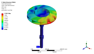
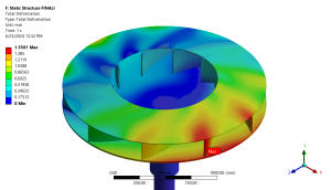
Figure 2: Total deformation contour from the Centrifugal Pump Impeller FSI CFD analysis, showing the maximum bending (red) on one side of the impeller disc.
The pressure contour shown in Figure 3 helps us understand why this uneven bending happens. As the water moves very fast through the pump’s spiral-shaped outer casing (called the volute), it creates very different pressures around the impeller. On one side, the water pushes very hard (high pressure, shown in red), while on other sides, it might even create a pulling or sucking effect (lower pressure, shown in blue). It is this big difference in pushing and pulling forces from the water that causes one side of the impeller disc to bend more than the others. The spiral design of the pump is necessary for good pumping efficiency, as it gradually increases pressure. The most important achievement of this Centrifugal Pump FSI Fluent simulation is that it directly links the uneven pressure distribution caused by the pump’s volute to the observed uneven deformation of the impeller. This vital connection allows engineers to understand the exact source of structural stress. By using this detailed information, designers can optimize the impeller’s thickness or material in specific areas to ensure it is strong enough to resist these uneven forces without being too heavy or stiff, leading to pumps that are both efficient and have a longer service life.
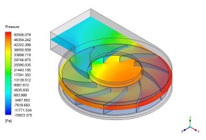
Figure 3: Pressure distribution contour within the pump, illustrating the varying Hydrodynamic Forces on the Impeller and their role in causing uneven deformation.


Reviews
There are no reviews yet.