

In fluid mechanics, cavitation is the formation and subsequent collapse of vapor bubbles inside a liquid when the local static pressure drops below the liquid’s vapor pressure. When these bubbles implode near a solid surface, they release shock waves and microjets, which cause noise, vibration, efficiency loss, and severe cavitation erosion.
Understanding its causes, impacts, and prevention strategies is essential for engineers working with pumps, turbines, and hydraulic systems. Today, advanced tools like ANSYS Fluent enable accurate cavitation CFD simulation, helping engineers mitigate damage or harness its effects for applications like ultrasound cleaning.
What is the Cavitation Phenomenon?
The cavitation phenomenon occurs naturally when high-speed fluid flows through restricted areas, creating regions of intense low pressure. While this process often damages marine propellers and turbines (see Fig.1), it also has useful applications. Cavitation ultrasound is widely used in medical treatments, such as shock wave lithotripsy for breaking kidney stones.
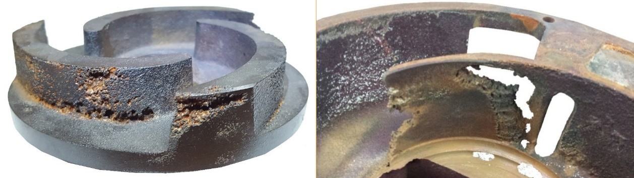
Figure 1- Pump impellor cavitation
Figure 2 illustrates flow behavior through a valve, showing how pressure changes affect normal flow, cavitation, and flashing. As fluid passes through the vena contracta, pressure drops sharply. If it falls below the vapor pressure (Pv), vapor bubbles form and later collapse as pressure recovers, causing cavitation damage. If the downstream pressure remains below Pv, flashing occurs.
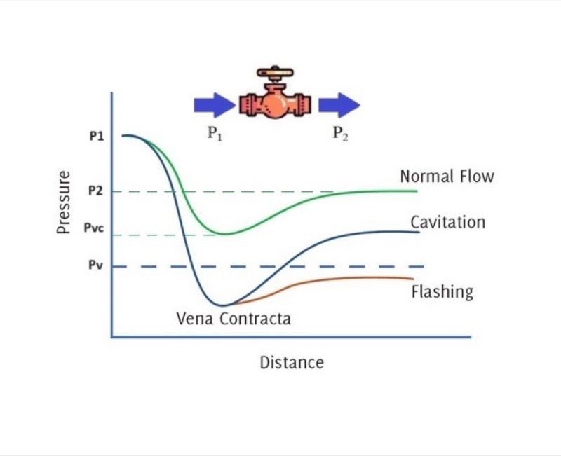
Figure 2- Pressure Behavior and Cavitation Phenomenon in a Valve
Cavitation vs Flashing
It is important to distinguish between cavitation and flashing in fluid mechanics. Proper valve design is essential to manage both.
| Feature | Cavitation | Flashing |
|---|---|---|
| Pressure Recovery | Pressure drops below Pv and then rises back above it. | Pressure drops below Pv and stays below it. |
| Bubble Fate | Bubbles form and violently collapse (implode). | Bubbles form and remain as vapor downstream. |
| Resulting Damage | Severe pitting and surface erosion. | Erosion is less localized, usually smooth wear. |
Cavitation Mechanism: How Cavitation Occurs Step by Step
Figure 3 illustrates the cavitation process, demonstrating how vapor bubbles form, collapse, and cause erosion in pipe walls or valve components:
- Vapor Bubble Formation: When local static pressure drops below the fluid’s vapor pressure, vapor bubbles form due to a rapid phase change from liquid to gas.
- Bubble Collapse (Implosion): As these bubbles travel into higher-pressure zones, they rapidly collapse (implode) under the surrounding liquid pressure.
- Supersonic Liquid Microjet Formation: The bubble implosion generates an intense shock wave, forming a high-speed liquid jet directed at nearby surfaces.
- Cavitation Damage (Surface Erosion): The immense force from these collapsing bubbles and microjets leads to cavitation erosion, causing pitting and wear over time.
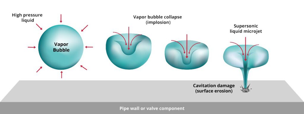
Figure 3- The Cavitation Process: From Bubble Formation to Surface Erosion
Cavitation Number
The cavitation number (σ), also known as the cavitation parameter, is a dimensionless value used to predict and analyze cavitation in fluid systems. It helps engineers assess whether cavitation in pump systems, turbines, or valves is likely to occur.
[latexpage] \sigma = \frac{P_{inlet} - P_{vapor}}{\frac{1}{2} \rho v^2}
Where:
- Pinlet = Local (or inlet) pressure (Pa)
- Pvapor = Vapor pressure of the fluid (Pa)
- ρ = Fluid density (kg/m³)
- v = Flow velocity (m/s)
Interpretation of Cavitation Number:
High σ (σ > 1) → Low risk of cavitation
Moderate σ (0.1 < σ < 1) → Possible cavitation, depending on system conditions
Low σ (σ < 0.1) → High risk of cavitation formation
Note: These ranges are indicative. The critical cavitation parameter heavily depends on the specific geometry and operating point
Effects of Cavitation
Before discussing prevention, engineers must understand the destructive cavitation effects. Common issues include:
- Cavitation Erosion: Severe pitting and material loss on solid surfaces.
- Noise and Vibration: Loud crackling sounds (often described as “pumping gravel”) and mechanical vibrations.
- Efficiency Loss: Significant drops in head and flow rate in pumps and turbines.
- Mechanical Failure: Damage to seals, bearings, and long-term structural fatigue.
How to Predict and Prevent Cavitation
Cavitation Analysis and CFD Simulation Tools
Advanced tools like ANSYS Fluent simulate flow conditions, pressure drops, and cavitation-prone areas. If your team needs expert help, you can use our CFD consultation services to analyze your hydraulic systems. Figures 4 and 5 showcase some of CFDLand’s website products. You can order CFD simulation projects from our platform to master these setups.
- Cavitation in Orifice Plate CFD Simulation, ANSYS Fluent Training – Learn how to simulate cavitation in an orifice plate using ANSYS Fluent, covering key parameters and best practices (Fig.4).
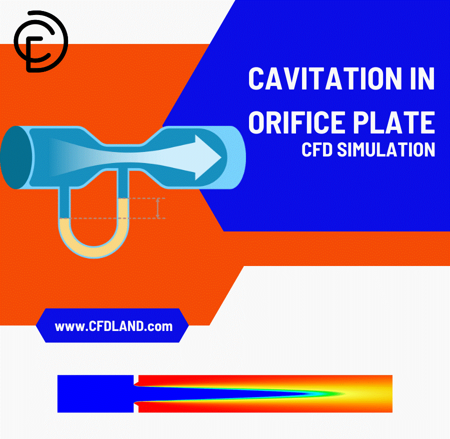
Figure 4- Cavitation in Orifice Plate CFD Simulation
Cavitation around Wedge CFD Simulation, Numerical Paper Validation – A detailed CFD simulation of cavitation around a wedge, validated with numerical research for accuracy (Fig.5).
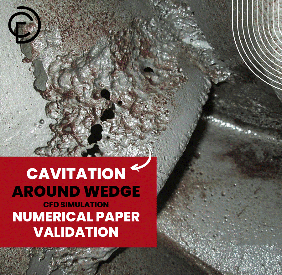
Figure 5- Cavitation around Wedge CFD Simulation
How to Prevent Cavitation
To stop cavitation damage in hydraulic systems, you must keep the local pressure above the vapor pressure. You can achieve this by:
- Increasing NPSHa: Raise the suction tank level or lower the pump elevation.
- Reducing Fluid Velocity: Increase the pipe diameter to slow down the flow.
- Redesigning Components: Use an inducer or redesign the impeller inlet to handle lower pressures.
- Reducing Friction: Avoid throttling valves on the suction side of the system.
- Temperature Control: Lower the fluid temperature to reduce its vapor pressure.
Pump Performance Curves (NPSH)
Manufacturers provide Net Positive Suction Head (NPSH) values to ensure that the pump operates safely. Cavitation happens when the NPSH available (NPSHa) is less than the NPSH required (NPSHr). (Keep Fig 6, 7, and 8 Images)
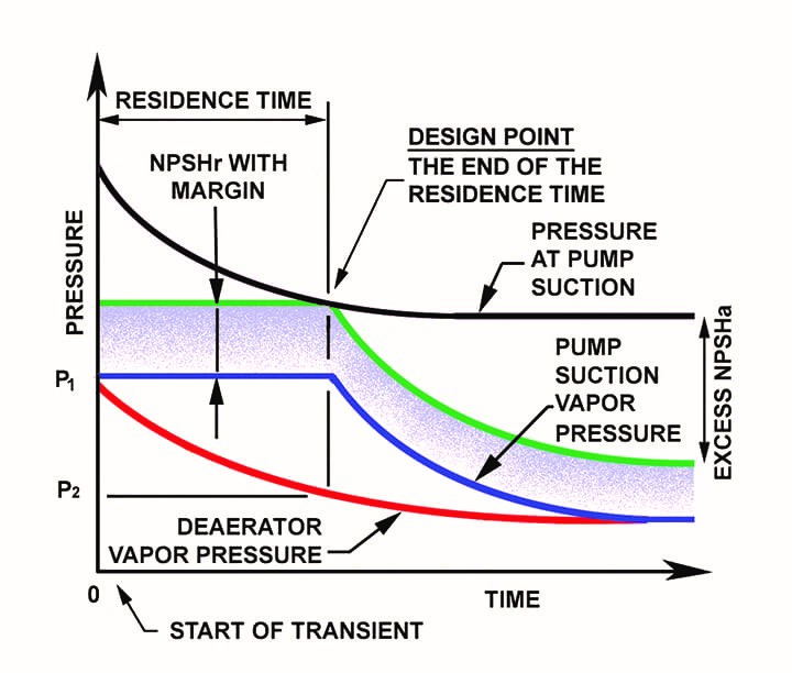
Figure 6- The relation between Cavitation and the NPSH of a pump
Cavitation generates high-frequency noise and vibrations, which can be detected using specialized sensors (Fig.7).
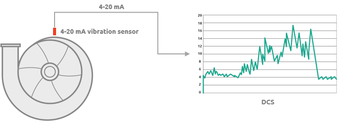
Figure 7- A typical application using a 4-20mA sensor.
Transparent test sections and high-speed cameras can help observe cavitation bubble formation in experimental setups (Fig.8).
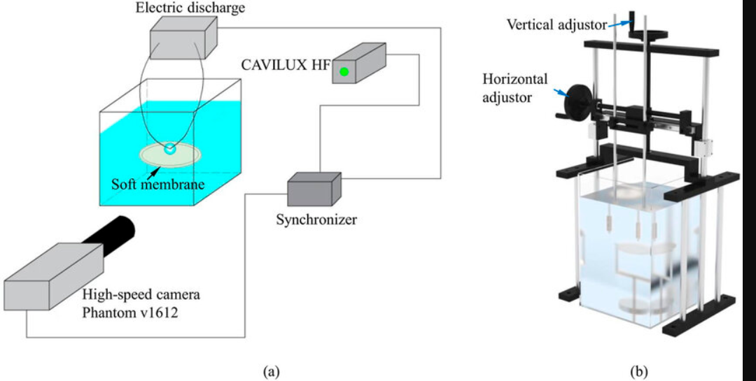
Figure 8- A schematic of the experimental setup for observing the behaviors of a spark-induced cavitation bubble near a soft membrane
Cavitation Models in ANSYS Fluent
In ANSYS Fluent, three cavitation models are available:
- Singhal et al. Model: Also known as the Full Cavitation Model, it incorporates cavitation effects into two-phase flows when using the mixture multiphase model.
- Zwart-Gerber-Belamri Model: Compatible with both the mixture and Eulerian multiphase models.
- Schnerr-Sauer Model: As the default cavitation model in ANSYS Fluent, it works with both the mixture and Eulerian models.
Cavitation models can be used to achieve the following:
- The Singhal et al. model can account for the effects of non-condensable gases in the flow.
- Both segregated and coupled solvers can be used.
- Cavitation models are fully compatible with dynamic mesh CFD simulation and non-conformal interfaces.
- For compressible liquids, density is defined using a User-Defined Function (UDF).
Limitations of Cavitation Models
- The Singhal et al. model is limited to a single cavitation process (one liquid phase).
- It is not compatible with the Eulerian multiphase model.
- It does not support the LES turbulence model.
- When using the implicit VOF multiphase model, if a sharp phase interface needs to be captured, turbulent effects can be disabled.
Important Considerations
Numerical solution stability in cavitation simulations is highly sensitive. Factors such as high pressure differences between inlet and outlet, large liquid-to-vapor density ratios, and high phase change rates can negatively impact the run. Inappropriate initial conditions often cause sudden crashes or a floating point exception.
The Singhal et al. model is not enabled by default. To use this cavitation model, the user must first activate the Mixture multiphase model, then enter the text command solve/set/expert and respond “yes” when prompted with “use Singhal-et-al cavitation model?” (Fig. 9). If the TUI command is not used, the setup panel turns out to be as shown in Figure 10. You must select Cavitation in the Mechanism of Phase Interaction panel.
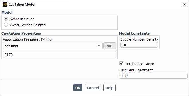
Figure 9- Singhal et al. model setting panel.
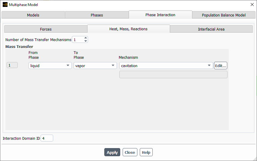
Figure 10- : Phase Interaction panel
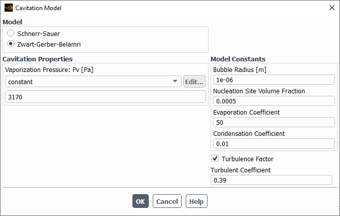
Figure 11- Zwart-Gerber-Belamri model selection
Conclusion
Understanding cavitation in fluid mechanics is crucial for industries relying on hydraulic systems. It directly affects the efficiency and lifespan of pumps, valves, and propellers. By calculating the cavitation number and monitoring system pressures, engineers can predict and prevent erosion, noise, and performance loss. Using advanced computational tools like ANSYS Fluent, which offers robust models like Schnerr-Sauer and Zwart-Gerber-Belamri, industries can accurately simulate phase changes. This ensures safer designs, reduced maintenance costs, and optimal fluid flow behavior.
FAQs
- What is the meaning of cavitation? Cavitation refers to the formation and collapse of vapor bubbles in a liquid when the local static pressure drops below the liquid’s vapor pressure. It causes efficiency loss and mechanical damage.
- What is the difference between cavitation and flashing? In cavitation, pressure drops below the vapor pressure and then recovers, causing vapor bubbles to collapse. In flashing, the pressure drops below the vapor pressure and remains there, meaning the liquid permanently turns into a vapor stream.
- What is the difference between cavitation and boiling? Cavitation is driven by a drop in pressure at a constant temperature. Boiling is driven by an increase in temperature at a constant pressure. Both processes create vapor bubbles in a liquid.
- How do I prevent cavitation in a pump? To prevent cavitation, you must increase the Net Positive Suction Head available (NPSHa). You can do this by raising the suction tank level, reducing fluid velocity, or removing flow restrictions on the suction line.
- What is the cavitation number? The cavitation number (σ) is a dimensionless parameter used to predict cavitation risk. A lower cavitation number indicates a higher likelihood of vapor bubble formation.
- How can computational tools help in cavitation analysis? Software like ANSYS Fluent allows engineers to simulate fluid flow, predict cavitation-prone areas, and test design changes before manufacturing.
- What is DEFINE_CAVITATION_RATE in ANSYS Fluent?
DEFINE_CAVITATION_RATEis a macro in ANSYS Fluent that allows users to write a User-Defined Function (UDF) to customize the mass transfer rate between the liquid and vapor phases during a cavitation CFD simulation. - What Cavitation Models are available in ANSYS Fluent? ANSYS Fluent offers the Singhal et al. Model (Full Cavitation Model), the Zwart-Gerber-Belamri Model, and the Schnerr-Sauer Model (Default).