

Floating point exceptions are common errors in ANSYS Fluent that can be broadly categorized into software-related and hardware-related issues. Software-related errors often stem from numerical instability, poor mesh quality, incorrect solver settings, inappropriate time step selection, and issues with user-defined functions (UDFs). Hardware limitations, such as using a 32-bit system or insufficient RAM, can also contribute to these errors. This article explores the causes of floating point exceptions in ANSYS Fluent and provides practical solutions to resolve them. Additionally, key aspects of Mesh Quality, including Skewness, Orthogonality, Smoothness and Aspect Ratio are discussed to enhance simulation stability. By the end of this guide, readers will gain a comprehensive understanding of floating point exceptions and effective strategies to mitigate them for optimized CFD simulations.
Floating Point Exception Error in ANSYS Fluent
The “Floating Point Exception” error is a frequent issue in CFD simulations conducted in ANSYS Fluent. This error signifies a numerical failure in the solver, often caused by invalid operations such as division by zero or numerical overflow. It can occur in various scenarios, including static simulations, transient analyses, and dynamic mesh simulations. Generally, there are types of problems which cases this error: software-related and hardware-related issues (Fig.1)
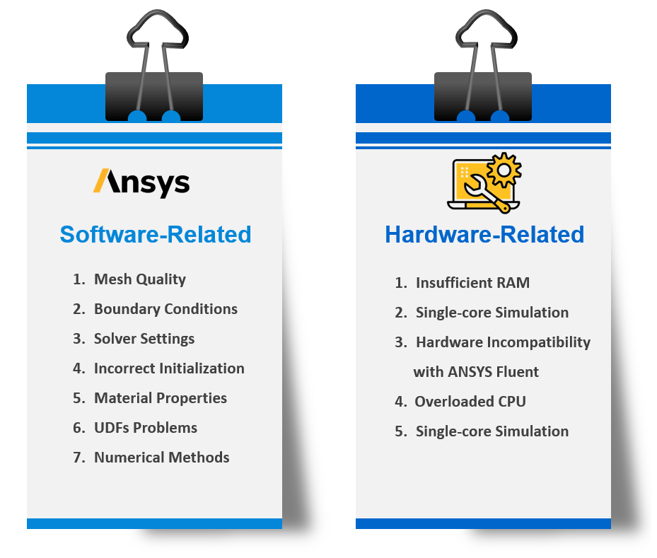
Figure 1- Causes of Floating Point Exceptions in ANSYS Fluent
It should be noted that Floating point exceptions can manifest in various forms, such as:
- Error at Node 0: Floating Point Exception: A common error indicating a numerical failure at the first computational node (Fig.2).
- Solver crash during initialization or iterations.
- Divergence in residuals or instability in the solution.
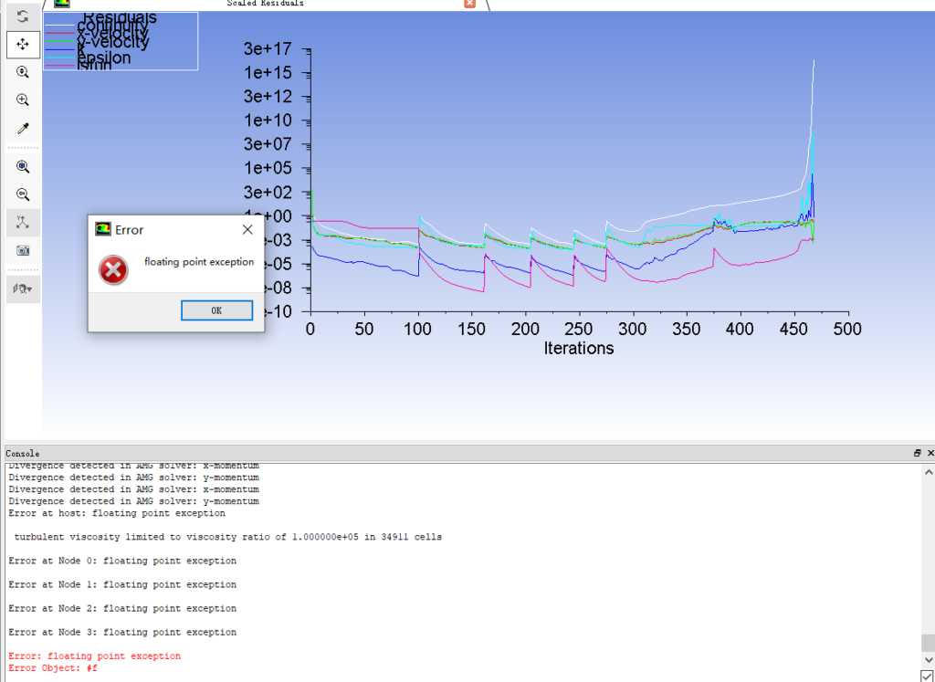
Figure 2- ANSYS Fluent Floating Point Exception Error
Hardware-Related Causes
Hardware-related issues are less common but can still cause floating point exceptions, particularly in large or complex simulations.
Insufficient Memory (RAM)
The memory required for a simulation depends on the mesh size, solver settings, and physical models. For example:
- A pressure-based solver in single precision mode with 1 million cells requires ~1 GB of RAM (The overall formula is that 1 GB RAM for each 1 Million Cells).
- Double-precision mode and additional models (e.g., turbulence, multiphase, chemical reactions) significantly increase memory requirements.
Solution:
- Upgrade to a 64-bit system with sufficient RAM (e.g., at least 16 GB for complex simulations).
- Use parallel computing to distribute the computational load across multiple processors.
Outdated Hardware
Using a 32-bit operating system or outdated processors can limit the solver’s ability to handle large datasets, leading to floating point exceptions.
Solution:
Upgrade to a 64-bit operating system and ensure your hardware meets Fluent’s recommended specifications.
Software-Related Causes
Software-related issues can significantly impact the stability and accuracy of CFD simulations in ANSYS Fluent, often leading to floating point exceptions. Poor Mesh Quality, Incorrect Boundary Conditions, Improper Solver Settings, Incorrect Initialization, Improper Material Properties, User-Defined Functions (UDFs) Problems, and Inappropriate Numerical Methods are the main Software-Related problems causes Floating Point Exception Error. In the following sections, we will examine each of these issues in detail and provide effective solutions to resolve these errors.
Mesh Quality in ANSYS Fluent
Since the Poor Mesh quality is one of the most critical factors which causes Floating Point Exception Error, we decided to focus on it deeply due to its special importance and position. If you need to know more about types of mesh prior to quality measurement factors, read our comprehensive guide on this.
A low-quality mesh can cause numerical instability, solver divergence, and in some cases, lead to a Floating Point Exception error. Therefore, assessing and improving mesh quality before running a numerical simulation is essential. There are some key metrics for evaluating Mesh Quality, including Skewness, Orthogonal Quality, Smoothness and Aspect Ratio, which help determine the accuracy, stability, and reliability of CFD simulations in ANSYS Fluent.
Skewness
A measure of how much a mesh cell deviates from its ideal shape (e.g., a perfect square or an equilateral triangle). A skewness’ of 0 is the best possible one and a skewness of one is almost never preferred. (Fig.3)

Figure 3- Skewness Mesh Metrics Spectrum
The Fig.4 illustrates an example of mesh cell skewness, showing how shape deviation affects CFD accuracy. Ideal cells, like equilateral triangles and squares (skewness = 0), ensure numerical stability. Moderate skewness (0.25–0.33) in right triangles and parallelograms introduces minor errors but remains acceptable. High skewness (≥0.5) in distorted triangles and quadrilaterals can cause numerical instability, making mesh refinement necessary for accurate simulations. The Fig.5 shows the grid skewness correction process over two iterations.
![Figure 4- Impact of Skewness on Mesh Quality in CFD Simulations[1]](https://cfdland.com/wp-content/uploads/2025/03/5-2.png)
Figure 4- Impact of Skewness on Mesh Quality in CFD Simulations[1]
![Figure 5- Iterative Skewness Correction in Mesh Generation[1]](https://cfdland.com/wp-content/uploads/2025/03/6-2.png)
Figure 5- Iterative Skewness Correction in Mesh Generation[1]
Orthogonality and Non-Orthogonality
In CFD meshing, Orthogonality and Non-Orthogonality refer to the angle between the normal vector of the shared surface of cells and the vector connecting the centers of cells.
Orthogonality occurs when the normal vector to the shared surface between cells is aligned with the vector connecting the cell centers, offering advantages like reduced numerical errors, higher stability, faster convergence, and proper flux distribution. This is commonly seen in rectangular and square structured meshes. In contrast, non-orthogonality involves an angle between the normal vector and the vector connecting the cell centers, leading to increased numerical errors, numerical diffusion, and the need for correction schemes (Non-Orthogonal Correction). Non-orthogonal meshes are often used in complex geometries, such as triangular meshes and slanted cells (Fig.6).
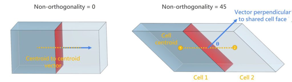
Figure 6- Representation of non-orthogonality mesh quality metric based on cell centroid and shared cell face
The table 1 compares orthogonality and non-orthogonality in CFD meshes, and the Fig.7 depicts the Orthogonal Quality Mesh Metric Spectrum, ranging from Unacceptable (0–0.001) in red to Excellent (0.95–1.00) in blue, highlighting the quality of mesh cells for numerical simulations. It is recommended to ensure mesh orthogonality by maintaining angles close to 90 degrees (orthogonal quality = 1.0) between cell faces and flow directions. Avoid meshes with angles closer to 0 degrees (orthogonal quality = 0), as they indicate poor alignment and lead to higher numerical errors, increased computational cost, and instability.
Table 1- Comparison of Orthogonality and Non-Orthogonality in CFD Meshes
|
Criterion |
Orthogonality |
Non-Orthogonality |
|
Angle Between Vectors |
Close to 0° (Ideal) |
Close to 90° (Poor) |
|
Non-Orthogonality Factor |
0 (Perfect) |
1 (Worst) |
|
Numerical Accuracy |
High (Stable solution) |
Low (Errors increase) |
|
Correction Needed? |
No |
Yes (Correction schemes required) |
|
Computational Cost |
Lower |
Higher (Due to corrections) |
|
Mesh Quality |
Good |
Poor (May need refinement) |
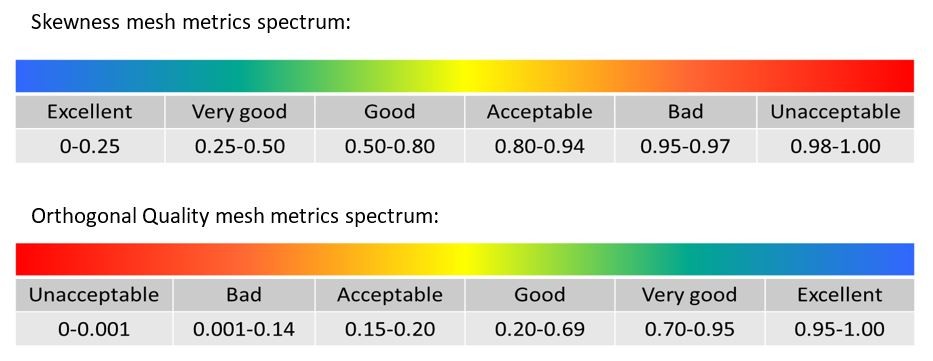
Figure 7- Orthogonal Quality Mesh Metric Spectrum
Smoothness
In ANSYS Fluent, smoothness is a key criterion for high-quality meshing. This criterion ensures that the size of adjacent elements does not vary significantly (Fig.8).
![Figure 8- Smoothness Criteria in Mesh[2]](https://cfdland.com/wp-content/uploads/2025/03/9.jpg)
Figure 8- Smoothness Criteria in Mesh[2]
Ideally, the size ratio between two neighboring elements should be below 2 and preferably around 1.2. Failing to meet this criterion can negatively impact solution convergence. This rule applies to both structured and unstructured meshes, making it essential to check in all cases. Therefore, when generating boundary layer meshes, it is crucial to maintain the recommended growth ratio to ensure smooth transitions and stable numerical solutions. The Fig.9 compares an initial mesh (a) with irregular spacing and element distribution to a smoothed mesh (b) with improved uniformity and alignment for better numerical accuracy and simulation performance.
![Figure 9- The Importance of Smoothed Meshes for Improved Element Distribution[3]](https://cfdland.com/wp-content/uploads/2025/03/1-1024x460.jpg)
Figure 9- The Importance of Smoothed Meshes for Improved Element Distribution[3]
Aspect Ratio
Aspect Ratio in CFD meshing refers to the ratio of the longest edge to the shortest edge of a mesh element. It indicates how stretched or distorted a cell is, affecting numerical accuracy and stability. However, it is important to note that if a mesh element is elongated in the direction of strong gradients, and the aspect ratio increases significantly in this direction, the mesh may encounter issues.
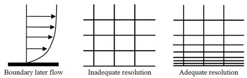
Figure 10- – The Importance of Aspect Ratio near the Boundary Layer
Large aspect ratios should always be avoided in important flow regions, where rapid changes, e.g., due to jets, flow separation, attachment, and recirculation, occur. Distorted cells in these regions can degrade solution accuracy and may result in poor convergence (Fig.11).
![Figure 11- Differently shaped cells with aspect ratios of 1.0 and their respective high aspect ratio cells[4]](https://cfdland.com/wp-content/uploads/2025/03/3-1.png)
Figure 11- Differently shaped cells with aspect ratios of 1.0 and their respective high aspect ratio cells[4]
Poor Mesh Quality: Solution
- Use Fluent’s Mesh Quality Diagnostic Tools to identify and fix problematic cells (Fig.11).
- Refine the mesh in critical regions, such as boundary layers or areas with high gradients.
- Ensure that the mesh covers all bodies of the geometry without gaps or cuts.
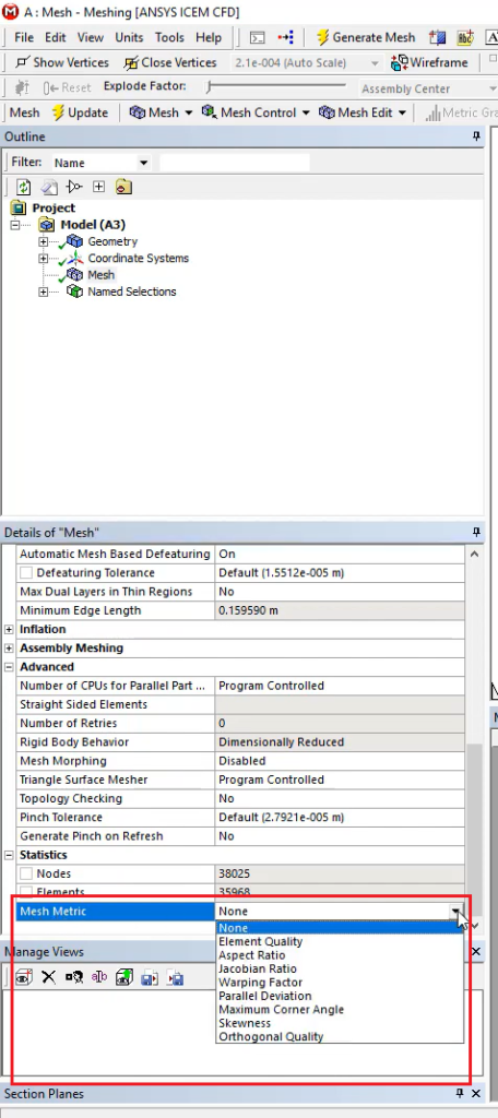
Figure 12- Mesh Quality Metrics Selection in ANSYS ICEM CFD for Identifying Element Quality and Potential Issues
Incorrect Boundary Conditions
Improper or conflicting boundary conditions can destabilize the solver and cause numerical divergence.
Examples:
- Applying incompatible conditions (e.g., velocity inlet with zero flow).
- Setting unrealistic pressure or velocity values.
Solution:
- Double-check all boundary conditions for physical realism and consistency.
- Ensure that the flow conditions match the problem setup
Solver Settings and Numerical Methods
Improper solver configurations, such as large time steps or incorrect numerical methods, can lead to floating point exceptions.
Common Issues:
- Using a time step size that is too large for transient simulations.
- Selecting a solver type (e.g., pressure-based vs. density-based) that does not match the problem physics.
- Relaxation factors that are too aggressive, leading to instability.
Solution:
- For transient simulations, reduce the time step size (<0.005 for most cases).
- Use the PISOmethod for transient analyses to improve stability.
- Adjust relaxation factors to stabilize the solution.Incorrect Initialization
Incorrect Initialization
in ANSYS Fluent can cause solver instability and floating point exceptions.
Common Issues:
- Unrealistic velocity/pressure fields
- Incorrect turbulence initialization
- Wrong reference pressure location
Solution:
Prevent errors, use Hybrid Initialization, set realistic values, and ensure correct phase volume fractions in multiphase flows. Proper initialization enhances solver stability and convergence.
Incorrect Boundary Conditions
Incorrect or unrealistic boundary conditions can lead to discontinuities and cause the solver to crash.
Solution:
Double-check all boundary conditions to ensure they are physically realistic and match the problem setup.
User-Defined Functions (UDFs)
Custom UDFs can introduce errors if not written or implemented correctly. For example, if a UDF calculates values outside the physical range or fails to account for zero denominators, it can trigger a floating point exception.
Solution:
- Debug UDFs to ensure that all variables are within a reasonable physical range.
- Test UDFs with simpler cases before applying them to complex simulations.
If you want to enhance your UDF writing skills, our UDF CFD Simulation tutorials, for instance, “Slip and Non-slip Flow Inside a 2D Microchannel CFD Simulation Using UDF” (Fig.13) Can level up you practical approach to implementing User-Defined Functions (UDFs) in ANSYS Fluent.
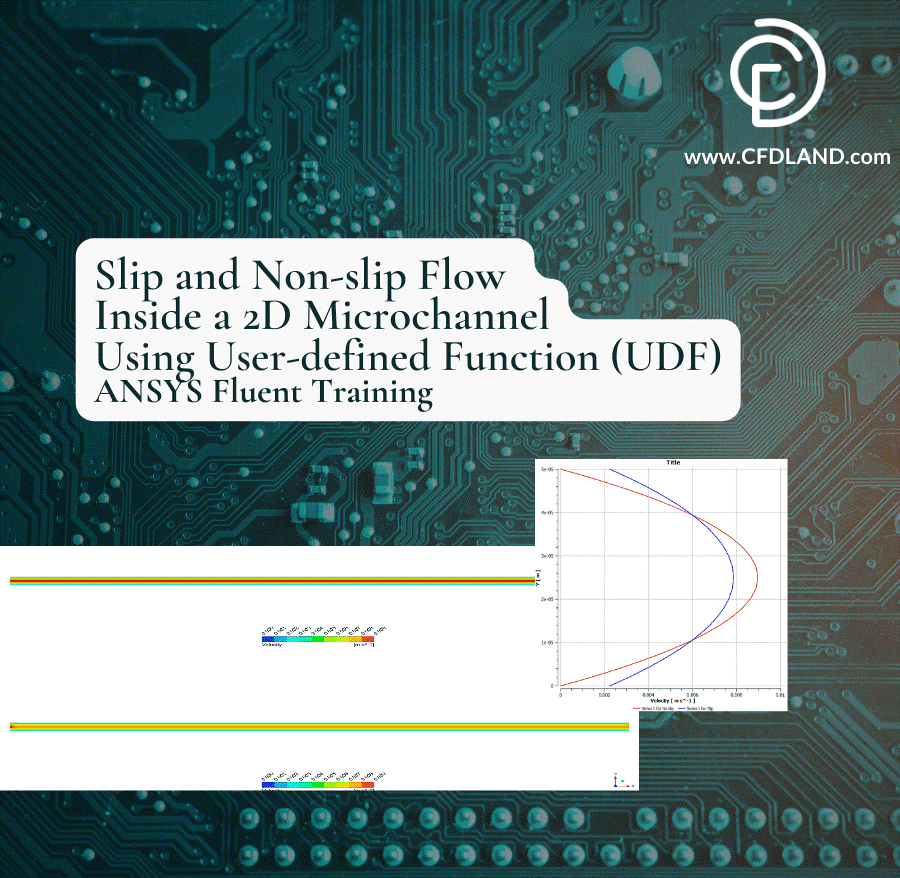
Figure 13- Slip and Non-slip Flow inside a 2D Microchannel CFD Simulation Using UDF
Conclusion
Floating point exceptions in ANSYS Fluent are a common challenge that arise due to both hardware and software-related factors. Hardware limitations such as insufficient RAM and outdated processors can hinder computational stability, while software-related issues—including poor mesh quality, incorrect solver settings, and inappropriate boundary conditions—often lead to numerical instability. Among these, mesh quality plays a crucial role in preventing floating point exceptions, with key parameters like skewness, orthogonality, aspect ratio, and smoothness significantly affecting solution accuracy and convergence. By addressing these factors through refined meshing strategies, careful solver configurations, proper initialization, and debugging of user-defined functions (UDFs), users can minimize numerical errors and enhance simulation reliability. Ensuring an optimized computational environment—both in terms of hardware upgrades and precise numerical setup—will ultimately lead to more stable and accurate CFD simulations in ANSYS Fluent.
FAQs
- What is a Floating Point Exception in ANSYS Fluent?
A numerical error caused by invalid operations like division by zero or overflow.
- What causes Floating Point Exception errors?
Poor mesh quality, incorrect solver settings, unstable boundary conditions, or insufficient hardware resources.
- How can I fix Floating Point Exceptions due to mesh quality?
Improve skewness, orthogonality, aspect ratio, and refine the mesh in critical regions.
- How does insufficient RAM cause Floating Point Exception errors?
If memory is too low, the solver may fail to process data, causing instability.
Related Articles
If you’re struggling with floating point exceptions in ANSYS Fluent, these related articles will help you resolve and prevent simulation errors:
-
ANSYS Fluent Convergence – Master convergence strategies to avoid the numerical instabilities that commonly trigger floating point exceptions. Learn how to properly monitor residuals, adjust under-relaxation factors, and implement solution stabilization techniques.
-
What is a Courant Number (CFL Number)? – Understand how CFL number settings directly impact simulation stability. Improper time step sizing is a leading cause of floating point exceptions, especially in transient simulations with complex physics.
-
ANSYS Fluent Boundary Conditions – Discover how proper boundary condition implementation prevents numerical errors. Many floating point exceptions originate from physically unrealistic boundary settings or incompatible condition combinations.
-
Introduction to User-Defined Functions (UDFs) in ANSYS Fluent – Learn UDF debugging techniques and best practices to eliminate code-related floating point exceptions. Poorly implemented UDFs are a common source of solver crashes and numerical instabilities.
Addressing these aspects of your simulation setup will significantly reduce the likelihood of encountering floating point exceptions and other numerical errors in your CFD projects.
Reference
[1] M. Song, C. Li, X. Guo, and J. Liu, “An adaptive gradient correction method based on mesh skewness for finite volume fluid dynamics simulations,” Physics of Fluids, vol. 37, no. 1, 2025.
[2] S. Shedage, “Numerical investigation of micro scale flows in narrow gaps,” PhD thesis, NITIE-National Institute of Industrial Engineering, 12 2014.
[3] N. Wang, L. Zhang, and X. Deng, “Unstructured surface mesh smoothing method based on deep reinforcement learning,” Computational Mechanics, vol. 73, no. 2, pp. 341-364, 2024.
[4] A. Lintermann, “Computational meshing for CFD simulations,” Clinical and biomedical engineering in the human nose: A computational fluid dynamics approach, pp. 85-115, 2021.