
Meshing in CFD: A Comprehensive Guide
Meshing, the technique of partitioning a computational domain into smaller, interconnected cells, is significantly used in computational fluid dynamics (CFD). It is the simulation’s backbone, and it influences accuracy, stability, and computational cost. This blog post explores the different mesh types used in CFD, outlining their characteristics, applications, and the importance of mesh quality in Simple words.
What is Meshing in CFD?
Meshing is the process of dividing a fluid domain into smaller, interconnected components called cells, forming the foundation for numerical flow simulations. These cells, along with nodes, faces, and edges, are fundamental elements of the mesh. A well-designed mesh accurately captures the geometry and flow physics, ensuring reliable results. Conversely, a poorly designed mesh can ruin the entire simulation. Figure 1 illustrates these mesh terminology components in both 2D and 3D. Nodes are points, faces are boundaries of cells (lines in 2D, squares in 3D), edges are boundaries between faces (lines in 3D), and the entire computational domain is made up of these interconnected elements grouped into zones. The type and density of the mesh—how many cells are used and how they are arranged—considerably impact the balance between accuracy and computational resources.
Tip: A denser mesh typically provides higher accuracy but requires more. It does not guarantee the reliability. This is where grid sensitivity analysis becomes crucial.
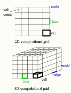
Figure 1: Mesh terminology in CFD
Types of Meshing
There are three primary mesh types used in CFD:
- Structured
- Unstructured
- Hybrid
Each has been created for distinct geometries, and it employs a variety of cell or element configurations. Typical cell types employed in mesh generation are depicted in the following image:
- In two-dimensions: Quadrilaterals, Triangles
- In Three-dimensions: Tetrahedra, Hexahedra, Pyramids, prisms with triangular bases (wedges), Arbitrary polyhedra
The dominant cell shape is frequently determined by the mesh type, which in turn affects the computational cost and accuracy of the simulation.
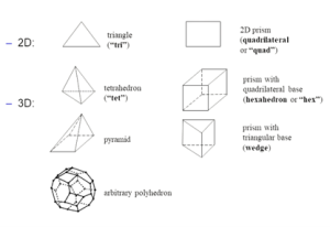
Figure 2: Typical mesh cell shapes in CFD
Structured Mesh
Structured meshes are characterized by an identical grid-like arrangement of cells, which are hexahedra in 3D and quadrilaterals in 2D. Implicit connectivity is established by this regular structure, which enables the identification of a cell’s neighbors by their indices. This simplifies algorithms and enhances computational efficiency. Structured meshes are particularly effective in simpler geometries. This configuration enables faster convergence, increased accuracy, and relatively low cell counts, particularly when cell skewness is reduced.
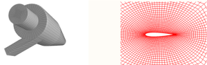
Figure 3: Structured grid produced in 2D & 3D simulations
However, complicated geometries are difficult for structured meshing to handle. It takes a lot of time and skill to generate these grids for complex designs, and multi-zone techniques.
Unstructured Mesh
Irregularly shaped cells, such as triangles (2D) and tetrahedra (3D), are used in unstructured meshes. Because of their adaptability, they can automatically mesh complex fluid volumes in complex geometries.
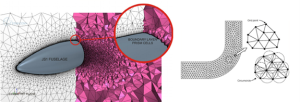
Figure 4: unstructured mesh visualization
Unstructured meshes have trade-offs even if they can easily handle complicated shapes. Increased computational costs result from the increasing number of higher cell counts, which are frequently three to four times larger than structured meshes. Skewness, different cell neighborhood interactions, and the grid’s non-orthogonal structure can all cause convergence to be delayed. However, advances are provided by developments in unstructured meshing, such as polyhedral meshes (Fig. 5). With more neighbors than tetrahedra, polyhedral cells are able to capture gradients with fewer cells, possibly even surpassing hexahedral meshes for recirculating flows.
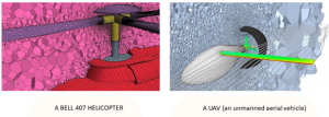
Figure 5: Polyhedra cells as a developed technique to reduce the number of unstructured cells
Hybrid Mesh
The advantages of both structured and unstructured methods are combined in hybrid meshes, which provide both geometric freedom and accuracy. While unstructured meshes manage diverse areas, they intentionally use structured meshes in areas with simpler geometry and predictable flow. This method maximizes accuracy and performance by utilizing both the flexibility of unstructured grids and the efficiency of structured grids. Hexahedra, tetrahedra, prisms, and pyramids are among the cell types commonly used in hybrid meshes to produce a smooth transition between various mesh sections. Semi-structured meshing is frequently used in near-wall regions to effectively resolve boundary layers by forming layers of structured cells. In less crucial regions, switching to different cell types away from the wall enables a more adaptable and computationally efficient mesh. For complex geometries that demand both precision and flexibility, hybrid meshes work especially well.
Tip: Pyramid and prism elements are often used in hybrid meshing for transitioning between different cell types.

Figure 6: Hybrid mesh as an efficient option for complex geometries
Mesh Density and Accuracy
In CFD, mesh density—the quantity of cells per unit volume—is essential. Higher precision is typically achieved with a denser mesh, but the computational cost goes up. Higher mesh densities are frequently needed in areas with curved surfaces or significant flow velocity gradients. Adaptive meshing methods dynamically modify the mesh density according to the behavior of the solution. As a result, the balance between accuracy and processing resources can be optimized by allowing for higher density in crucial locations and lower density elsewhere. This trade-off needs to be taken into account while configuring a CFD simulation.
Impact of Element Size on Mesh Density
The selected element size has a direct impact on mesh density. A denser mesh with smaller components is more accurate but requires more computing power. This relationship is illustrated in the following figures, which show how different element sizes impact the final mesh for both a basic rectangular prism and a circular shape.
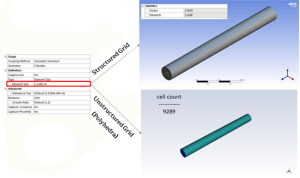
Figure 7: Cell`s shape effect on number of elements in a pipe CFD Simulation
Comparing the cylindrical and rectangular prism examples, we observe a similar trend: decreasing element size consistently leads to a substantial increase in the number of mesh elements. While the specific cell counts differ due to the geometry variations, the fundamental principle remains the same.
Mesh Quality and Solution Accuracy
The accuracy and stability of CFD simulations are considerably affected by mesh quality. Inaccurate findings, sluggish convergence, or even simulation failure might come from poor mesh quality. Aspect ratio, smoothness, skewness, and element form are important components of mesh quality. A higher quality mesh and more dependable outcomes are produced by well-shaped elements with suitable aspect ratios and less skewness.
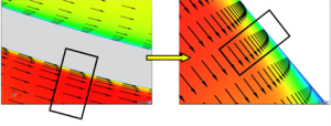
Figure 8: Comparison of flow solutions obtained with a “bad” (highly skewed) mesh and a “good” (well-shaped) mesh. The “bad” mesh leads to inaccurate and distorted results, while the “good” mesh produces a smoother and more realistic flow field

Figure 9: Comparison of hexahedral (Hex) and triangular (Tri) meshes for simulating an inviscid co-flow jet. The Hex mesh exhibits better resolution and accuracy, especially in regions with sharp gradients.
Conclusion
Here is a table summarizing the key points about meshing in CFD:
| Mesh Type | Characteristics | Advantages | Disadvantages | Applications |
| Structured | * Regular, grid-like arrangement of cells | * Computational efficiency due to implicit connectivity | * Difficult to handle complex geometries | * Simpler geometries where efficiency and accuracy are prioritized |
| * Hexahedral cells in 3D, quadrilaterals in 2D | * Higher accuracy due to reduced cell skewness | * Time-consuming and skill-intensive to generate for complex designs | ||
| Unstructured | * Irregularly shaped cells (triangles in 2D, tetrahedra in 3D) | * Adaptability to complex geometries | * Increased computational costs due to higher cell counts | * Complex geometries where flexibility is crucial |
| * Automatic meshing of complex fluid volumes | * Skewness and non-orthogonal structure can cause convergence delays | |||
| Hybrid | * Combines structured and unstructured meshes | * Combines advantages of both structured and unstructured meshes | * Complex geometries requiring both precision and flexibility | |
| * Structured meshes in areas with simpler geometry, unstructured elsewhere | * Geometric freedom and accuracy |
Choosing the right mesh type is crucial for successful CFD simulations. Structured meshes offer efficiency and accuracy for simpler geometries, while unstructured meshes provide flexibility for complex shapes. Hybrid meshes combine the best of both worlds, optimizing performance and accuracy. Understanding the nuances of each mesh type, the importance of mesh quality, and the impact of element size empowers CFD practitioners to make informed decisions, leading to more reliable and efficient simulations.
Related Blogs