
For simulating complex fluid flow in various applications, it is essential to use Computational Fluid Dynamics (CFD) tool. When dealing with moving parts or intricate geometries, traditional meshing tools such as conformal, non-conformal, and deforming mesh options can struggle to reach accuracy and efferent results since they may have more computational costs and are time-consuming. This is where Overset Mesh Technology offers a flexible and powerful solution for these challenges.
This blog represents the overset mesh definition, its usage in CFD software such as Ansys Fluent, and its pros and cons compared with other meshing tools. If engineers and researchers gain enough understanding to implement an overset method correctly, they can benefit from its technology and advanced applications in industry to ease complex problems into simple and cost-effective tasks.
Overset Method
An overset mesh, or chimera methodology, allows for overlapping mesh domains without difficulty and independently of one another. For example, in each section, the child mesh can move freely relative to a background mesh that can remain fixed or move in a different manner. As an alternative to conformally connected cell zones and non-conformal interfaces, this method provides another means of building a complete mesh. It is beneficial for simulating moving objects, such as aircraft with rotating propellers or vehicles with moving wheels, without the need to re-mesh frequently.
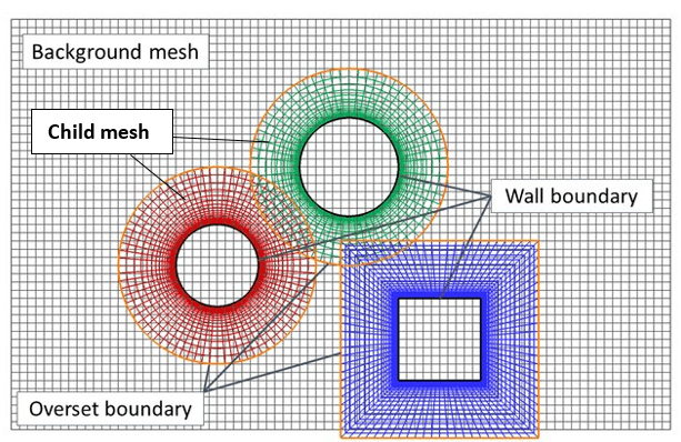
Showing different name selections in overset mesh methodology
Link: Pölzlbauer P, Kümmel A, Desvigne D, Breitsamter C. Numerical investigation of an optimized rotor head fairing for the racer compound helicopter in cruise flight. Aerospace 2021;8:1–21. https://doi.org/10.3390/aerospace8030066.
The Importance of Overset Mesh
Meshing techniques, like conformal and non-conformal, sometimes cause problems in generation, especially when the geometry has multiple bodies that move. Other techniques such as sliding and dynamic mesh, can lead to high computational costs. Overset technique, which has been added and improved in Ansys Fluent since version 2019, can resolve this issue by keeping the meshes independent, allowing for easier manipulation and better accuracy when dealing with dynamic systems.
Applications of Overset Mesh in Industry
Overset mesh has diverse applications across various industries, with Ansys Fluent at the forefront of facilitating complex simulations.
- Aerospace Engineering: simulating aircraft with moving parts like ailerons, landing gear, or propellers.
- Automotive Engineering: simulating interactions between rotating wheels and the body of a vehicle.
- Marine Applications: simulating the movement of propellers and rudders in relation to the hull of a ship.
- Wind Energy: simulating wind turbine blades.
As these applications demonstrate, overset mesh in Ansys Fluent plays a critical role in modern engineering.
Overset Mesh Fluent
By implementing overset meshes in Ansys Fluent, the limitations of conformal meshing and sliding interfaces are overcome, as remeshing would be necessary for every movement or deformation of a part. In addition to ensuring accurate prediction of flow fields around moving bodies, Fluent’s overset capabilities make simulations more efficient.

“Water Entry of Dimpled Sphere CFD Simulation” is one of the Dynamic Mesh projects done by CFDLAND. Simulated by ANSYS FLUENT.
Overset Boundary Condition Fluent
In Ansys Fluent, understanding how to set overset mesh is crucial to achieving the best results. The following points are significant for establishing an overset mesh in Fluent:
1.Defining the Overset Regions
In Fluent, users must define the background and child zones. Each zone has its own mesh that doesn’t conform to the other, and the solver automatically handles the interpolation between them. After the flow is initialized, Fluent establishes the necessary connectivity between the meshes automatically. Dead cells are those that fall outside of the computational domain.
2.Overset Domain Connectivity
Fluent establishes connectivity between the participating zones when an overset interface is initialized. These are the three steps:
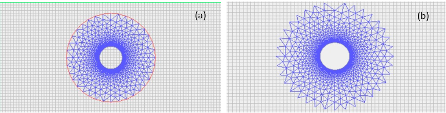
Hole Cutting
Hole cutting describes the process of marking dead cells outside the flow region (i.e., inside bodies and outside of the computational domain). The process involves marking all cells that contain physical boundaries (walls, inlets, outlets, symmetry, etc.), as well as seed cells outside the flow region, which are then filled with dead cells by flooding. By applying flood filling to the overset mesh, maximum overlap is achieved.
Link: Canonsburg TD. ANSYS FLUENT User’s Guide. Knowl Creat Diffus Util 2012;15317:724–46.
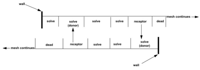
Overlap Minimization
Through overlap minimization, extra solve cells are converted into receptor cells, and unnecessary receptor cells are turned into dead cells. Solve cells are designated as those where the flow equations are solved. In receptor cells, data is interpolated from another mesh. Donor cells, in which receptors receive their information, are a subgroup of solve cells. When a solve cell finds a suitable donor cell with a higher donor priority, it becomes a receptor cell. The donor priority is higher for smaller cells by default. By moving the mesh interface to a location where the meshes are more similar, the quality of the solution is improved.
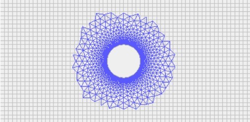
Overset Component and Background Meshes After Overlap Minimization.
Link: Canonsburg TD. ANSYS FLUENT User’s Guide. Knowl Creat Diffus Util 2012;15317:724–46.
Several donor priority methods can be specified in order to control where the overset interface appears. If you use the text user interface command define/overset-interfaces/options/donor-priority-method, you can specify whether the donor priority is determined by the cell size or the boundary distance. With overlap minimization, donor priority is determined by cell size (default) if the component mesh resolution is fine near walls and increases away from walls to spacings similar to-or larger than the background mesh. It may be more efficient to use a donor priority based on boundary distance rather than overlap minimization based on cell size if the meshes have similar and nearly identical resolutions.
Donor Search
In order to establish domain connectivity, the donor search is the last step. To find valid solve cells for each receptor, Fluent searches other meshes. Receptor cells’ centroid, along with its connected solve cells, serve as donor candidates for each receptor. A successful donor search requires at least one valid donor cell in each receptor and at least four in the overlap of both meshes. Also, there must be adequate overlap between the meshes to maintain continuity.
Valid Overlap definition
Link: Canonsburg TD. ANSYS FLUENT User’s Guide. Knowl Creat Diffus Util 2012;15317:724–46.
Overset Mesh vs. Sliding Mesh
Each meshing technique has its limitations and advantages. Comparing overset mesh with other popular methods, it highlights why overset is so valuable.
- Sliding Mesh: Simulations of rotating components, like fans or turbines, are performed using this method. It can be more cumbersome to create sliding meshes when multiple parts move relative to each other, since precise interface definitions are required. However, an offset mesh handles these interactions more flexibly, making it easier to set up complex simulations in Fluent.
click to access Sliding Mesh CFD
- Dynamic Mesh: In order to handle moving or deforming boundaries, dynamic meshes are used. While dynamic meshes are useful, they require re-mesh as parts move or deform, which can introduce errors or increase computational costs. The overset mesh avoids this problem by keeping the meshes independent, so it is preferred in situations with multiple moving parts.

“Falling Ball Into Water (Dynamic Mesh) CFD Simulation” is one of the Dynamic Mesh CFD projects done by CFDLAND. Simulated by ANSYS FLUENT.
- Structured vs. Unstructured Mesh: It is versatile enough to be used in a broad range of CFD simulations since it works with both structured and unstructured meshes. This flexibility makes it easier to adapt the mesh to the geometry of the problem.
Conclusion
Engineers and researchers have revolutionized fluid flow simulations involving moving parts and complex geometries with Overset Mesh Technology. Traditional meshing techniques, including conformal and dynamic meshes, pose many challenges that this method eliminates. Overset meshes are implemented in Ansys Fluent to enhance simulation accuracy, and to reduce computational costs and simplify the modeling process for dynamic systems. Overset mesh has proven invaluable for simulating real-world motion and interaction between components in the aerospace, automotive, and marine industries. The power of this advanced technology allows engineers to perform more flexible, precise, and efficient simulations across a wide range of engineering disciplines, advancing innovation across the board.
It can be beneficial for students and companies to collaborate with CFDLAND experts since they have experience in a wide range of CFD fields and projects. With ANSYS FLUENT software, you will be able to simplify your work and achieve high-quality results.
2 thoughts on “Overset Mesh Technology”
Can I ask a quick question about your site?
Roheify
Hello!
Thank you for reaching out to us. We’re happy to help with any questions you have about our site. Please feel free to ask your question, and we’ll do our best to assist you.
Looking forward to hearing from you!
Best regards,
CFDLAND Group