
A butterfly valve is a common device used to control or stop fluid flow in a pipe. It uses a rotating disk to block the flow path. Understanding the forces and flow patterns created by this disk is critical for designing valves that are efficient and reliable. A Butterfly Valve CFD simulation is the best engineering tool for this job. Using ANSYS Fluent, we can see exactly how the flow behaves as the valve opens and closes. This is especially important for predicting the torque needed to operate the valve and identifying risks like noise and vibration. This report details a Butterfly Valve Dynamic Mesh CFD simulation, with the analysis of hydrodynamic forces guided by the reference paper [1].
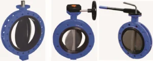
Figure 1: A real-world Butterfly valve for industrial applications
Simulation Process: Modeling the Butterfly Valve Fluent Simulation
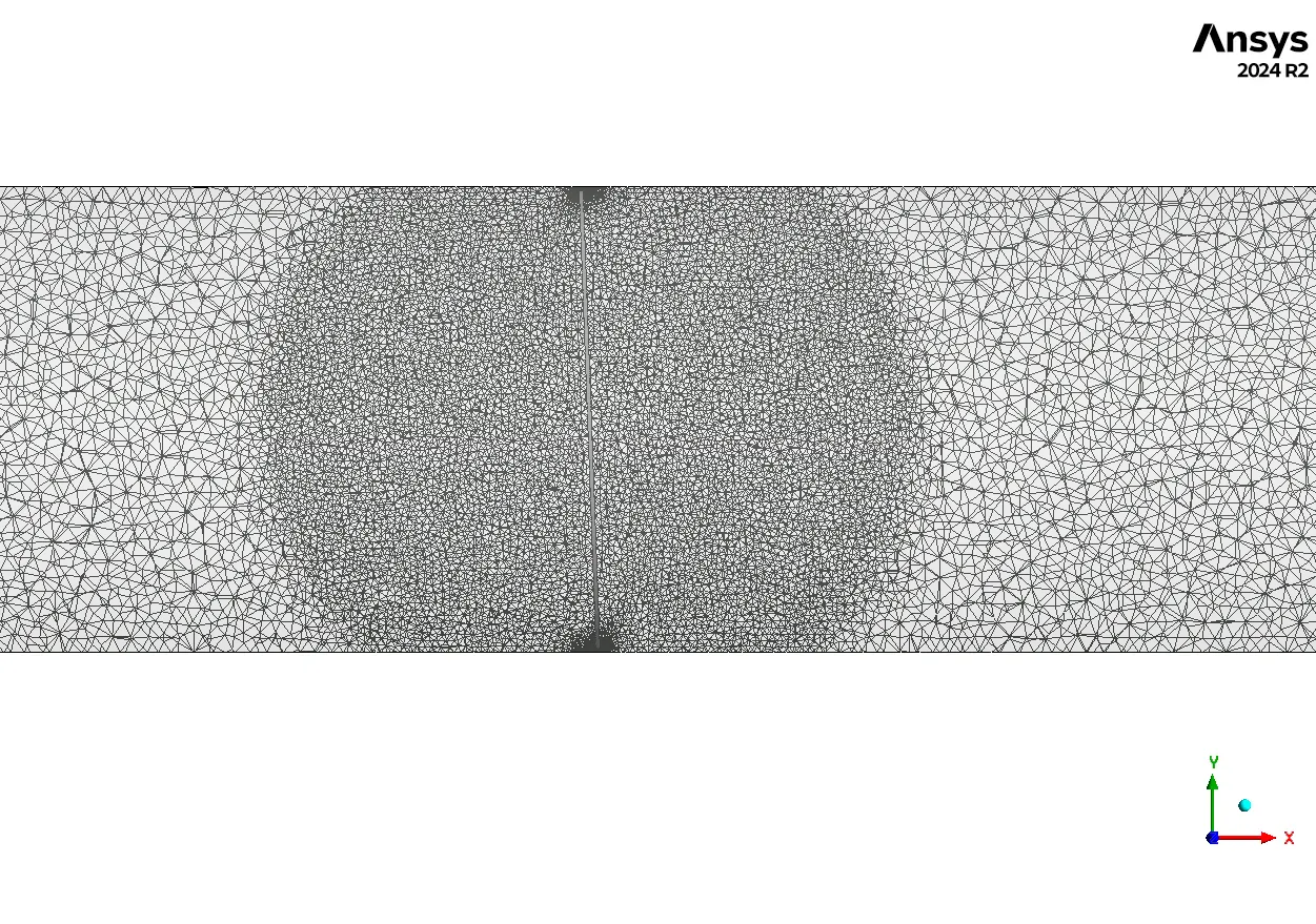
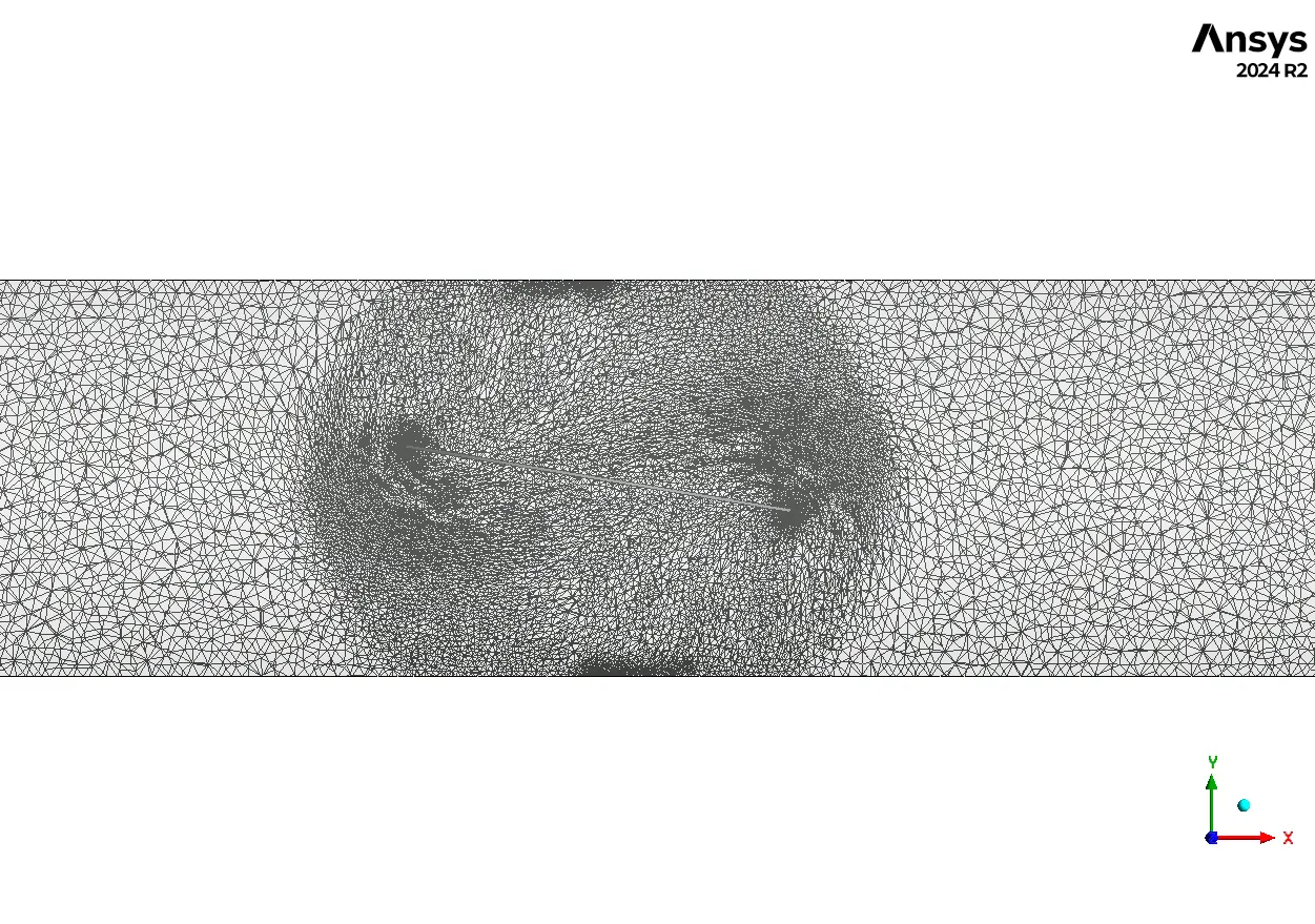
To begin, the 3D model of the Butterfly Valve Fluent geometry was filled with an unstructured mesh. This type of mesh is very good at adapting to the complex curves of the valve disk and pipe.
To simulate the opening and closing motion, a User Defined Function (UDF) was written. This custom code tells Fluent exactly how to rotate the valve disk over time using a smooth, sinusoidal motion. The simulation was run as transient, meaning it calculates the flow at many small-time steps to capture the effects of the continuous movement. The most important feature used was the Dynamic Mesh model. As the UDF rotates the disk, the mesh cells around it stretch and deform. The Remeshing technique was enabled, which automatically rebuilds the mesh in areas where it gets too distorted. This is essential for keeping the simulation stable and accurate while the valve is moving.
Post-processing: CFD Analysis, How Valve Motion Creates Pressure and Velocity Changes
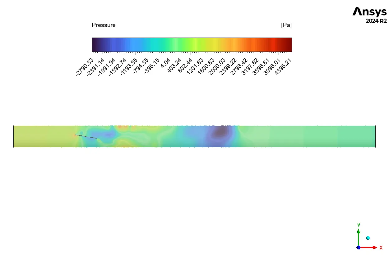
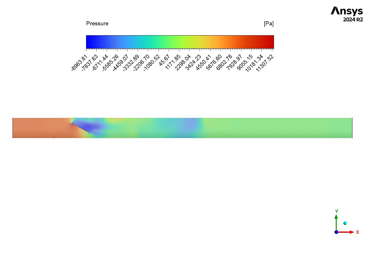
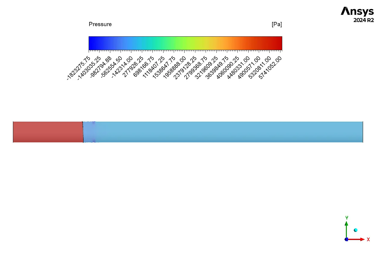
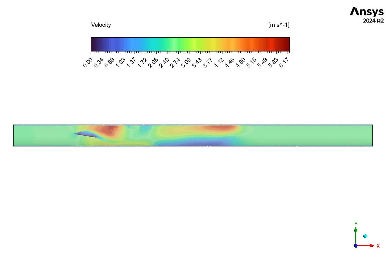
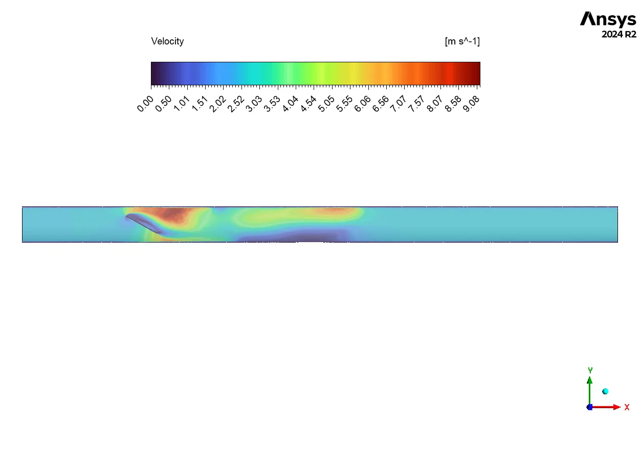
The simulation results provide a clear, substantiated story that begins with the valve’s motion, which is the “cause” of all the complex fluid behavior. As the UDF code rotates the disk to a partially closed position, the disk becomes a major obstruction in the flow path. This obstruction has two main effects. First, it physically blocks the incoming fluid, forcing it to stop and pile up. This is proven by the pressure contour in Figure 2, which shows a large area of high pressure (red, up to 4392.21 Pa) on the upstream face of the disk. Second, the obstruction forces the fluid to squeeze through the small gaps between the edge of the disk and the pipe wall. As the flow is squeezed into this smaller area, it must accelerate to a very high speed. The velocity contour in Figure 3 confirms this, showing jets of high-velocity fluid (red, up to 6.17 m/s) forming in these gaps.

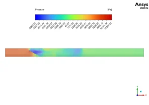
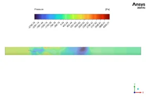
Figure 2: Pressure distribution from the Butterfly Valve CFD simulation at 30° and 45° opening angles.
This combination of high pressure on one side and high-velocity jets on the other has a direct and measurable “effect” on the valve’s performance and the downstream flow. The pressure difference between the high-pressure upstream face and the low-pressure downstream side (blue, down to -2790.33 Pa) generates a powerful turning force, or torque, on the disk. This is the hydrodynamic torque that the valve’s actuator must be strong enough to overcome. Furthermore, the high-velocity jets that shoot past the disk do not continue smoothly. They create large, swirling vortices in the downstream area, which are clearly visible in the velocity animation. These vortices represent significant energy loss, which causes the overall pressure drop across the valve and can lead to real-world problems like pipe vibration and noise. The most significant achievement of this Butterfly Valve Dynamic Mesh CFD simulation is the ability to precisely link the transient motion of the disk to the resulting hydrodynamic torque and downstream flow instability, providing critical data for designing actuators and predicting valve performance throughout its entire operational cycle.

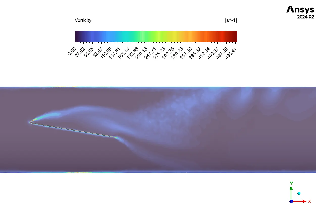
Figure 3: Velocity field from the Butterfly Valve Fluent simulation, showing high-speed jets at a 45° opening.


Reviews
There are no reviews yet.