


This study shows how we used Fluid-Structure Interaction (FSI) to study what happens to a centrifugal pump impeller when it spins in water using ANSYS Fluent and ANSYS Structural. Centrifugal pumps are super important in many industrial applications like water supply systems, oil and gas, chemical processing, and HVAC systems. When the pump impeller spins, it creates fluid forces that push against the impeller blades causing tiny structural deformations. Our one-way FSI analysis uses computational fluid dynamics (CFD) to calculate these pressure forces and then sends them to a structural solver to find out how much the steel impeller bends or twists. This approach works great when deformations are small and don’t really change the flow patterns. We used the Multiple Reference Frame (MRF) method to model the rotating domain at 1000 rpm and applied proper material properties including Young’s modulus and Poisson’s ratio to get accurate results. Understanding these FSI effects helps engineers build better pump designs with improved mechanical integrity, longer service life, higher efficiency, and less vibration and noise. This refrence paper was our guide through this FSI CFD study:
- Reference [1]: Babayigit, Osman, et al. “Numerical identification of blade exit angle effect on the performance for a multistage centrifugal pump impeller.” EPJ Web of Conferences. Vol. 92. EDP Sciences, 2015.
Figure 1: Centrifugal Pump impeller connected to the shaft
Simulation Process
This study focuses on the net force applied to the centrifugal pump impeller by the water. It is called one-way FSI analysis. Thus, it requires both Fluent and Structural modules. Initially, the flow pattern is predicted by the solution of computational zone, considering 1000 rpm impeller. The results are then transmitted to the Structural module to explore interaction and its effect on the propeller. Multi Reference Frame (MRF) applies the rotational motion to the propeller in Fluent solver. Notably, steel properties including poisson ratio and Young`s modulus are defined in ANSYS Structural.
Post-processing
The total deformation results show us something really interesting about how the disc-like part of this pump bends during operation. Looking at the colorful pattern, we can clearly see that the deformation isn’t the same everywhere – one side of the disc (the red and orange area) bends much more than the other sides. The maximum bending is only about 1.56 millimeters, which sounds tiny, but this small amount actually matters a lot! This uneven bending happens because the water pressure pushes differently on different parts of the disc as it spins. The really neat thing is how the inner part of the disc stays almost perfectly still while the outer edges do most of the bending. This makes sense because the disc is attached firmly to the shaft in the middle, so it can’t move much there, but the edges are free to flex a bit like the end of a diving board.
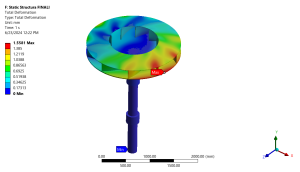
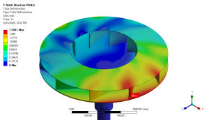
Figure 2: Total deformation contour showing maximum displacement of 1.5581 mm
The pressure contour in the third image helps explain why we get this uneven bending pattern. As water moves through the pump’s spiral-shaped outer casing, it creates very different pressures around the disc – from a strong pushing force to actually pulling or sucking. It’s this huge difference in pushing and pulling that makes one side of the disc bend more than the others. The spiral design of the pump creates a gradually increasing pressure as water moves around the casing, which is exactly what we want for pumping efficiency. But this pressure difference also causes that uneven deformation we saw earlier. Engineers have to find a perfect balance – the disc needs to be strong enough not to break or bend too much, but if it’s too rigid and heavy, the pump wastes energy. This simulation helps designers find that sweet spot where the pump works efficiently but also lasts a long time without breaking down.
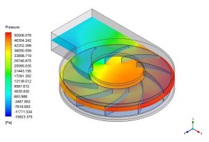
Figure 3: Pressure distribution within the pump


Reviews
There are no reviews yet.