


Modern electronic circuits produce large amounts of thermal energy during normal operation. If an enclosure cannot remove this heat, the internal components will quickly overheat and fail. To prevent this severe problem, engineers use advanced Electronics Box cooling CFD software to design safe ventilation systems. By performing a highly accurate Electronics Box cooling fluent simulation, designers can clearly visualize how cooling air travels around hot printed circuit boards. It is very important to note that this specific project is strictly an educational demonstration of fluid thermodynamics. A complete CFD Analysis of Electronics Box cooling using ANSYS Fluent allows manufacturers to test different fan positions and vent sizes before they physically build the metal enclosure. The software solves complex mathematical equations to predict the exact airflow speed and the maximum component temperatures. Understanding these invisible aerodynamic and thermal forces is essential for creating highly reliable hardware. To deeply learn how heat travels through solid copper wires and moving air, please carefully explore our comprehensive Heat Transfer tutorials.
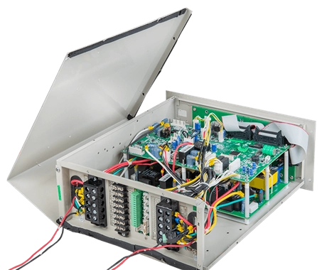
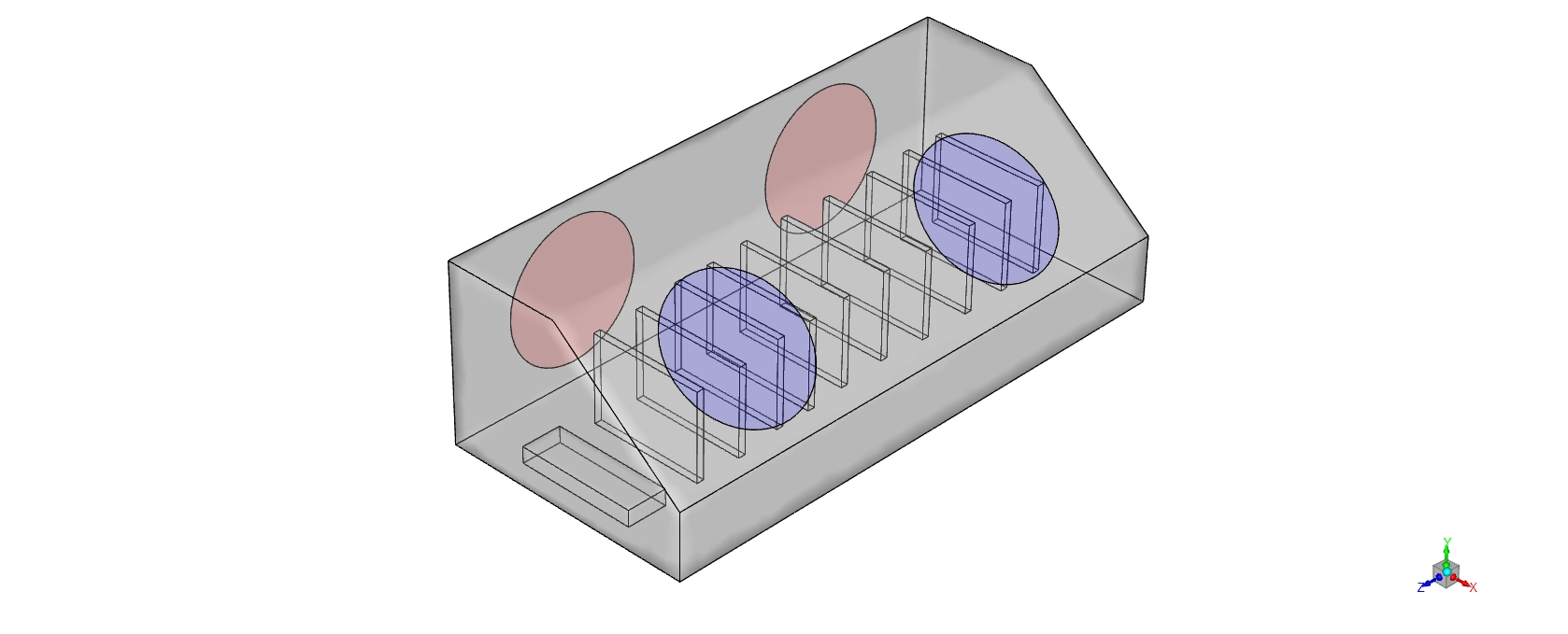
Figure 1: A schematic drawing of the protective electronics enclosure holding sensitive circuit boards.
Simulation Process: 3D Geometry and Thermal condition
To perform this exact Electronics Box cooling ANSYS Fluent project, we created a complete 3D computational domain of the sealed box. This virtual geometry contains a row of vertical circuit boards and internal copper elements. To measure the heat transfer perfectly, we divided the empty fluid space and the solid structures into exactly 1,770,251 tetrahedral cells.
Inside the Electronics Box cooling fluent setup, we defined specific thermal boundary conditions. We programmed the main inlet to provide warm air at exactly 318.706 K (45.56 °C). This represents a severe summer operating environment. Next, we applied a massive volumetric heat generation rate of exactly 40,682.489 W/m³ directly to the internal copper elements. This exact number represents the electrical energy lost as heat when power travels through the circuits. The software then uses these exact inputs to calculate the complex forced convection process.
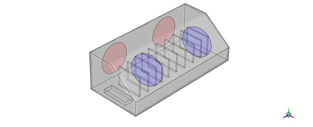
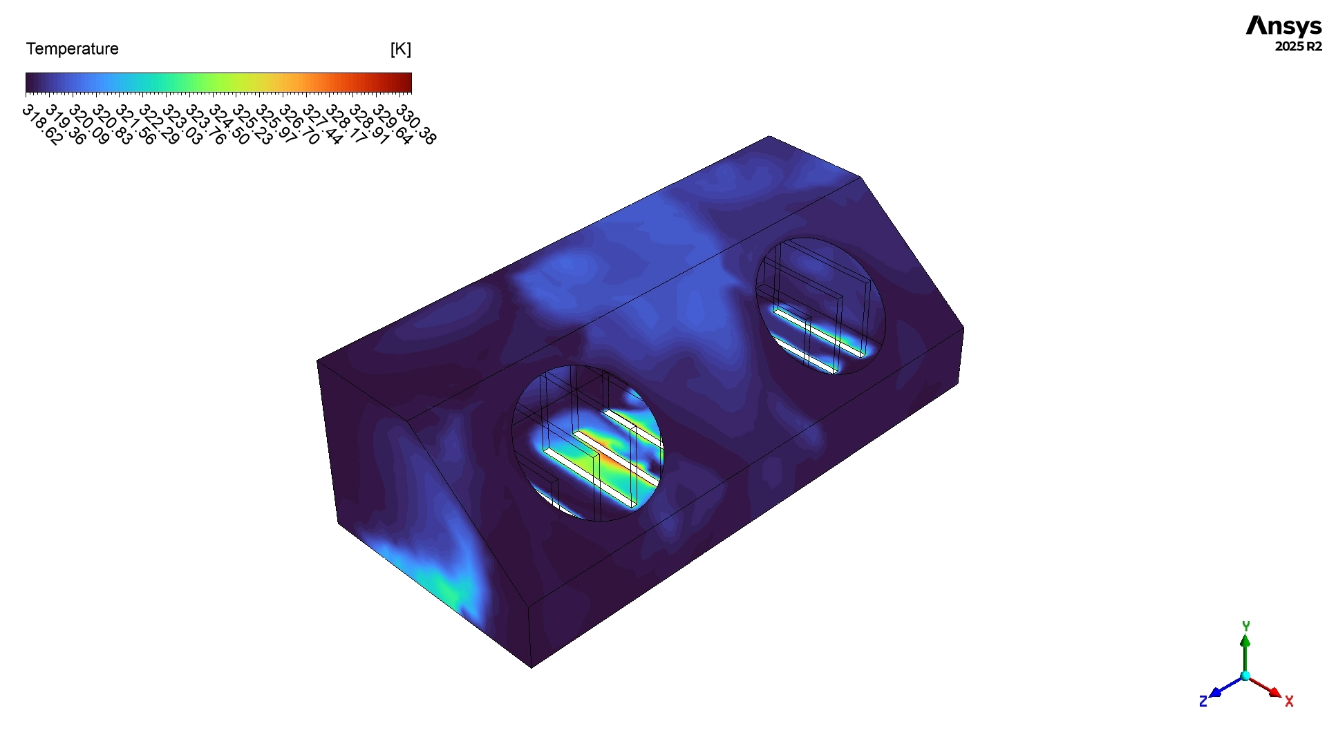
Figure 2: The 3D computational representation showing the 1.7 million tetrahedral cells used for thermal calculation.
Post-processing: Analysis of Temperatures and Pathlines
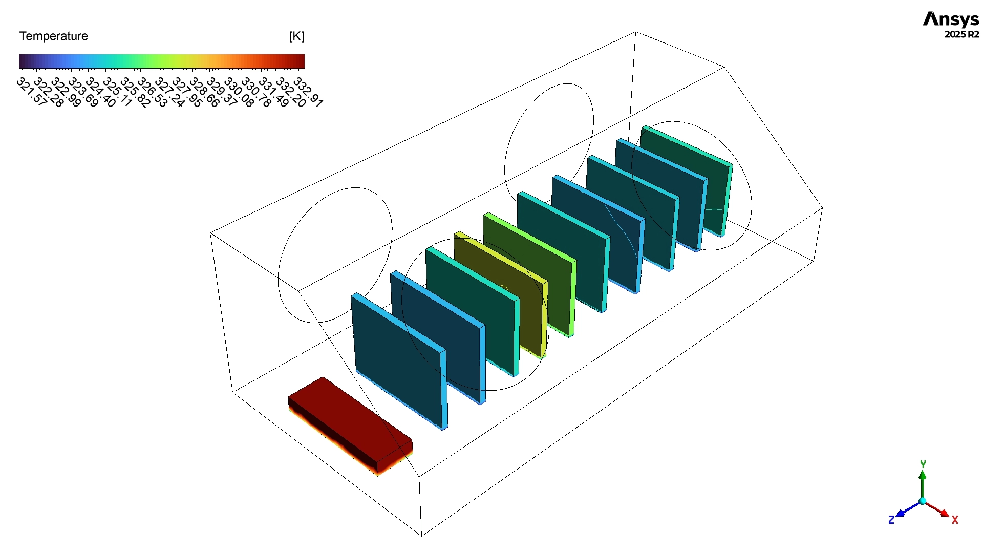
To truly evaluate the safety of this thermal management system, we must perform a very accurate and coherent analysis of the calculated data. We look closely at the temperature contours and the velocity pathlines to understand the cooling physics. We begin by reading the mathematical temperature data calculated by the software. The numerical results show that the internal heat-generating circuit boards reach an area-weighted average temperature of exactly 326.219 K (53.07 °C). Massive Engineering Achievement: This thermal result represents a huge success for the product design. Most standard electronic chips suffer physical damage if they exceed a strict limit of 85 °C. Because the components in this simulation only reach 53.07 °C, the engineers have secured a massive and safe thermal margin of nearly 32 °C. Furthermore, the overall cooling box average temperature remains safely at 319.578 K (46.43 °C). This means the exterior walls of the enclosure remain cool enough for human operators to touch safely. The data also reveals that the air exits the outlet vent at exactly 319.450 K (46.30 °C). Because the outlet air is only 0.74 °C warmer than the inlet air, we can scientifically prove that the system pushes a very large volume of air through the box, quickly washing the heat away before it can build up.
Table 1: Area-Weighted Average Temperatures inside the Enclosure
| Location | Temperature (°C) |
| Outlet | 46.30 |
| Components | 53.07 |
| Cooling Box Average | 46.43 |
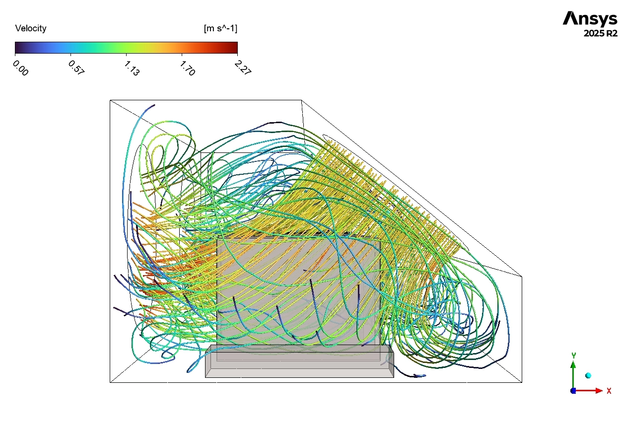
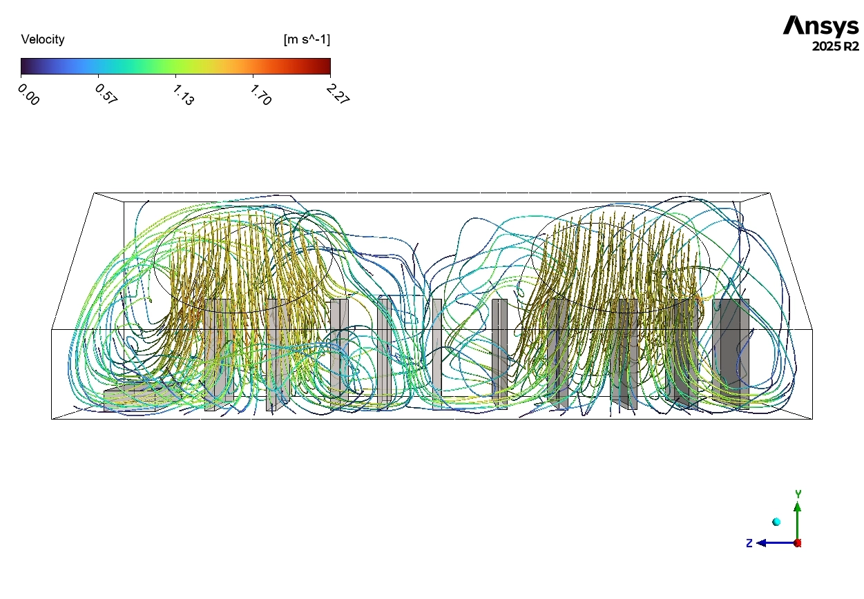
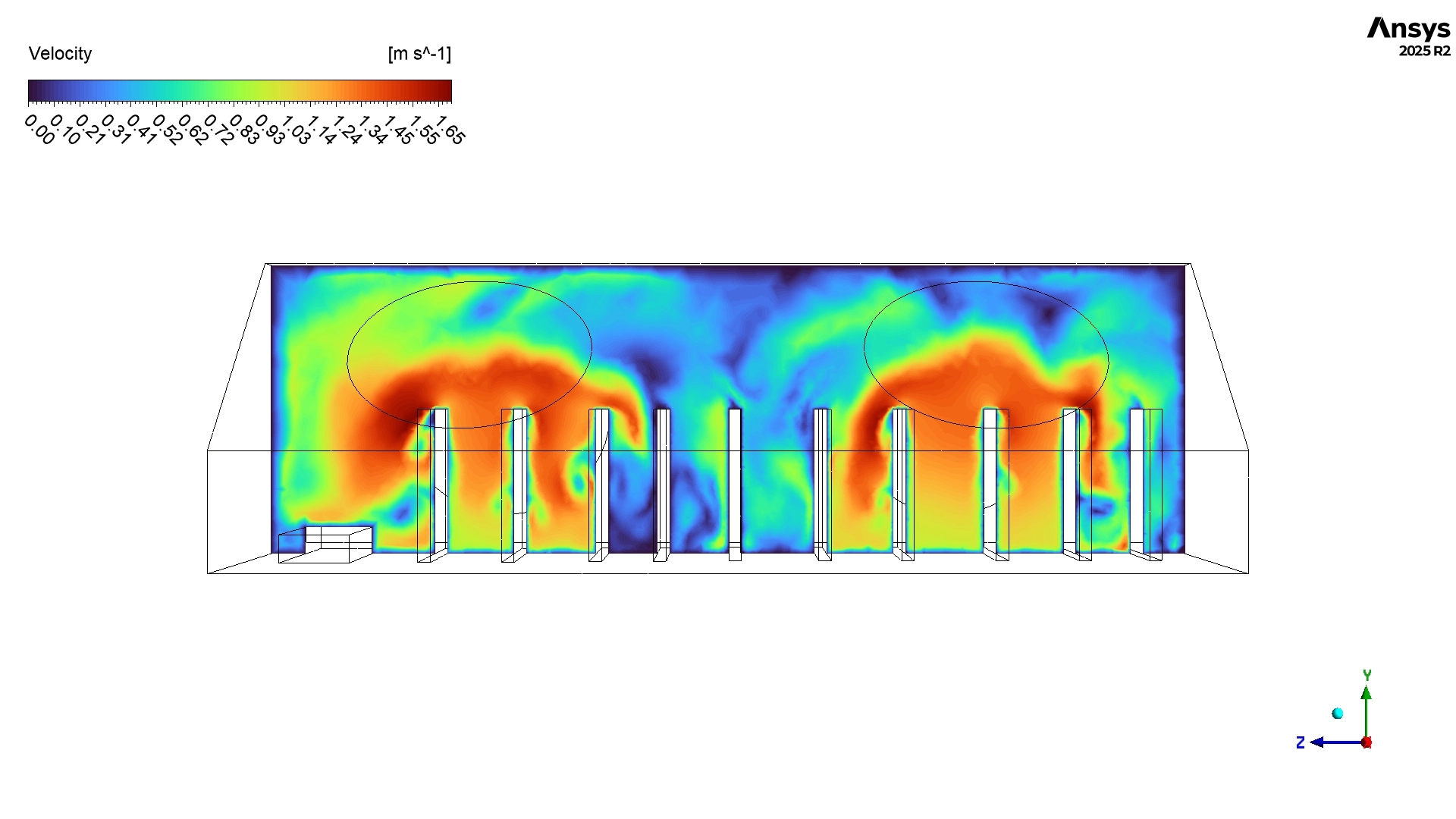
After proving the thermal safety, we must deeply analyze the aerodynamic behavior using the velocity pathlines. These colorful lines show the exact physical route the air takes from the inlet to the outlet. A large portion of the fresh air flows easily around the outside of the circuit board array. In these open spaces, the pathlines show blue and cyan colors, which represent a slow, gentle velocity between 0.50 m/s and 1.13 m/s. This gentle flow provides stable convective cooling. However, the fluid physics change drastically when the air travels directly between the circuit boards. The geometry contains very narrow gaps measuring only 5 to 10 mm wide. According to the physical law of continuity, when a fluid enters a smaller area, its velocity must increase. The exact simulation pathlines perfectly prove this law. Inside these tight gaps, the pathlines change to yellow and orange colors, proving the air rapidly accelerates to a much faster speed between 1.70 m/s and 2.27 m/s. This fast flow is highly beneficial because it aggressively pulls thermal energy away from the hot component surfaces.

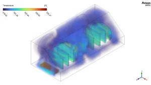
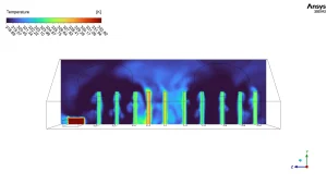
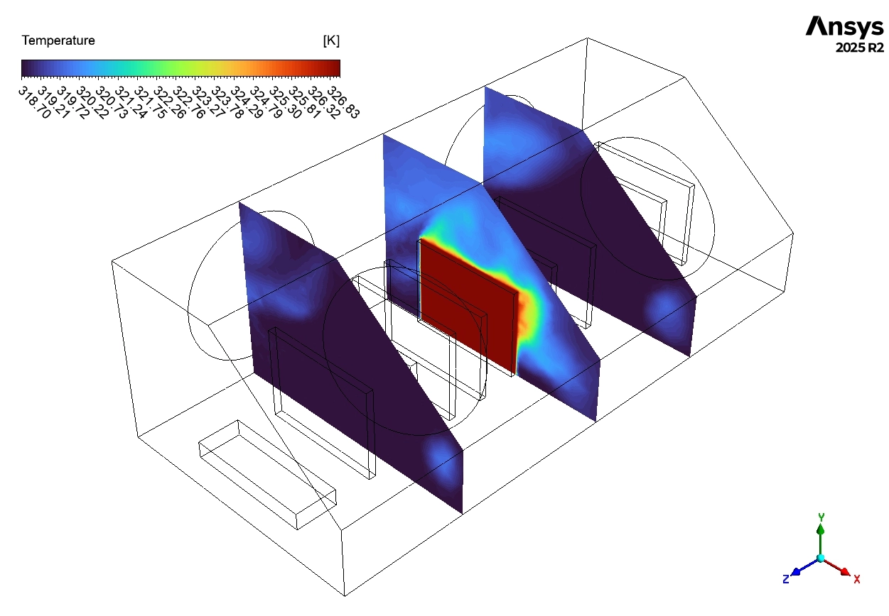
Figure 3: Static temperature contour displaying the thermal boundary layers and heat distribution (Scale: 318.65 – 333.27 K).
Despite this excellent cooling between the boards, the pathlines reveal severe aerodynamic flaws in the upper corners of the box. The simulation displays tight, spinning circular pathlines rotating slowly at 0.3 to 0.8 m/s. These are dangerous recirculation zones. Inside these zones, the air gets trapped by the geometry and rotates continuously instead of leaving the box. Over a long period, this trapped air will absorb heat and create localized hotspots. Additionally, the pathlines clearly show that the incoming wind completely bypasses several specific circuit boards, leaving them in stagnant, slow-moving air. While the current maximum temperature of 326.219 K is safe, these stagnant zones represent a poor design. To optimize this enclosure, engineers must install small internal plastic flow guides. These guides will physically block the recirculation zones and force the fast-moving air directly toward the stagnant circuit boards, ensuring a perfectly balanced thermal environment.
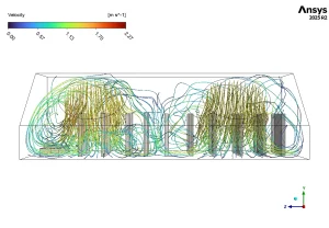
Figure 4: Velocity pathlines tracking the accelerated airflow between narrow board gaps and the spinning recirculation zones in the corners (Scale: 0.00 – 2.27 m/s).
Frequently Asked Questions (FAQ)
- What is volumetric heat generation in CFD?
- A: Volumetric heat generation is a mathematical setting in ANSYS Fluent. It represents the exact amount of thermal energy produced by a solid object, like a copper wire or microchip, while electricity flows through it. It is measured in Watts per cubic meter (W/m³).
- Why does the air speed up between the circuit boards?
- A: In fluid mechanics, air follows the law of continuity. When a large volume of moving air is forced into a very narrow gap between two boards, the physical area shrinks. To push the same amount of air through, the velocity must physically increase.
- What are recirculation zones, and why are they bad for electronics?
- A: Recirculation zones are areas where air spins in tight circles instead of flowing straight to the exit vent. These zones are bad because the trapped air absorbs heat continuously, creating a dangerous hotspot that can eventually damage the electronic chips.


Reviews
There are no reviews yet.