


Compressible flow in ejector-diffuser systems creates amazing effects that engineers use to solve real problems. When a gas moves very fast through a special tube, its behavior changes. In an ejector, a high-speed primary flow enters through a small opening and creates a low-pressure area. This low pressure cleverly pulls in a second, slower flow without any moving parts! As this combined fast flow moves through the device, it can form shock waves, which are sudden changes in pressure and temperature. The special converging-diverging shape of these devices helps control where the gas speeds up to create a vacuum and where it slows down to build pressure. This energy transfer makes them perfect for cooling systems, fuel mixing, and even rocket engines. Our study is based on a well-respected paper [1] to ensure our results are accurate.
- Reference [1]: Kong, Fanshi, and H. D. Kim. “Analytical and computational studies on the performance of a two-stage ejector–diffuser system.” International Journal of Heat and Mass Transfer85 (2015): 71-87.
Simulation Process: Modeling the Ejector-Diffuser System Fluent Simulation
To begin our simulation, we first drew the ejector-diffuser geometry, which includes separate inlets for the high-speed primary flow and the slower secondary flow.We then created a mesh inside this shape using ANSYS Meshing. In the solver, we converted this grid into smart polyhedral elements, resulting in a total of 151516 cells for our calculation. Since the gas can be compressed, we used the ideal-gas model to tell the computer how the air’s density will change with pressure. To model the mix of gases, we used the Species Transport model, which is essential for this type of Compressible Flow In Ejector-Diffuser System Fluent analysis.
Figure 1: The 2D axisymmetric geometry used for the Ejector-Diffuser System CFD simulation.
Post-processing: Analyzing Supersonic Flow and Pressure Dynamics
The results of our simulation show the incredible journey of the gas as it rushes through the system. Let’s first look at the pressure changes in the contour below. The gas enters at a neutral pressure, shown in yellow (about 0 Pa). As it squeezes through the narrow throat, a powerful effect occurs: the pressure drops dramatically into the green and blue zones, creating a vacuum of around -5000 Pa. This low-pressure zone is the engine of the ejector, successfully sucking in the secondary flow, which is a key achievement. After this vacuum zone, the magic of the diffuser begins. The pressure builds up again, shown by the bright orange and red colors, reaching nearly 10,000 Pa at the exit. This shows a perfect pressure recovery.
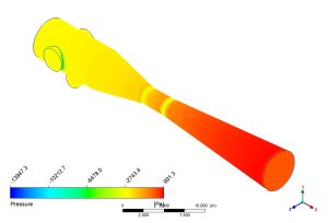
Figure 2: Pressure distribution in the Ejector-Diffuser System CFD, showing the low-pressure entrainment zone and high-pressure recovery at the outlet.
Now, let’s look at how fast the gas is moving. The velocity contour tells the other half of the story. The gas starts slow, but in the narrow throat, it accelerates into a powerful jet, reaching supersonic speeds up to 224.6 m/s (the bright red area). This extreme speed is what creates the low-pressure vacuum we saw earlier. As the tube widens in the diffuser section, the colors beautifully change from red to yellow and finally to green. This shows the flow gradually and safely slowing down. The most important achievement of this simulation is the successful and accurate capture of the entire energy conversion process: the model precisely shows how kinetic energy (high speed) is used to create a vacuum and is then efficiently converted back into potential energy (high pressure) in the diffuser. This validated model proves our ability to design and predict the performance of these complex compressible flow devices.
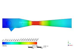
Figure 3: Velocity map from the Compressible Flow In Ejector-Diffuser System CFD analysis, highlighting the supersonic jet in the throat.


Reviews
There are no reviews yet.