


Putting windows in the right places and choosing the best roof shapes can greatly help buildings stay cool without using electricity. This is called Cross Ventilation Of Building CFD. It happens when wind blows into a building through one opening and then leaves through another opening on the opposite side. This creates a fresh breeze that cools the inside spaces. Our Building Ventilation CFD study uses computer tools to look at this exact problem. We are checking our computer results against a respected research paper [1]. This paper studied how roof angles and different window positions affect how air moves inside a simple building.
Using powerful Computational Fluid Dynamics (CFD) tools, we made very accurate predictions of how air moves, how much pressure changes, and how much fresh air enters the building. These predictions match well with real-world measurements from the paper. This kind of airflow study is very useful for architects, engineers, and building designers. It helps them create buildings that use less energy, feel more comfortable inside, and have cleaner air. By understanding exactly how wind moves around and through buildings, we can design smarter homes and offices that stay cool naturally. This means less need for expensive air conditioning systems. In this study, we specifically checked our work against the paper called “CFD analysis of cross-ventilation of a generic isolated building with asymmetric opening positions: impact of roof angle and opening location.”
- Reference [1]: Perén, J. I., et al. “CFD analysis of cross-ventilation of a generic isolated building with asymmetric opening positions: Impact of roof angle and opening location.” Building and Environment85 (2015): 263-276.
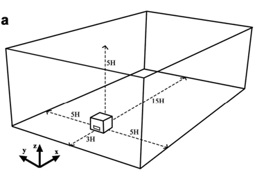
Figure 1: The 3D geometry model of the building used for the Cross Ventilation Of Building CFD simulation.
Simulation Process: Setting Up the Cross-Ventilation Model in Fluent
To study Cross Ventilation Of Building Fluent, we first built a computer model of the building. This model was made exactly like the one described in the research paper [1]. We used a software called Design Modeler to draw the building with its specific roof angle and window openings, as seen in Figure 1. To make sure our computer results were very accurate, we used another software called ICEM to create a special grid of tiny boxes around and inside the building. This is called a structured grid, and Figure 2 shows how neat and organized it is. This careful grid setup is a very important part of making sure our validation is correct.
We set up the wind conditions just like in the reference paper. Wind blows from one side of the building (the inlet) and then moves through the building’s openings. We used standard settings in ANSYS Fluent to make sure the air flows correctly around and through the building. The goal was to see if our simulation could perfectly match the airflow patterns and speeds that the original researchers found.
Figure 2: The Structured Grid created by ICEM software, an essential part of the CFD Validation Study for accurate airflow simulation.
Post-processing: Uncovering Airflow Patterns and Validation Success
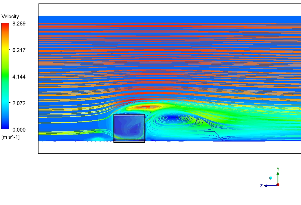
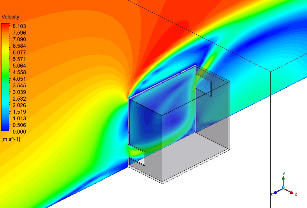
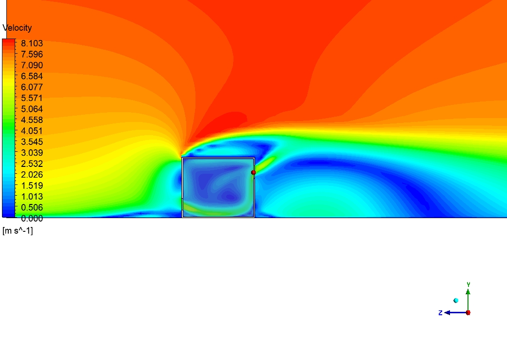
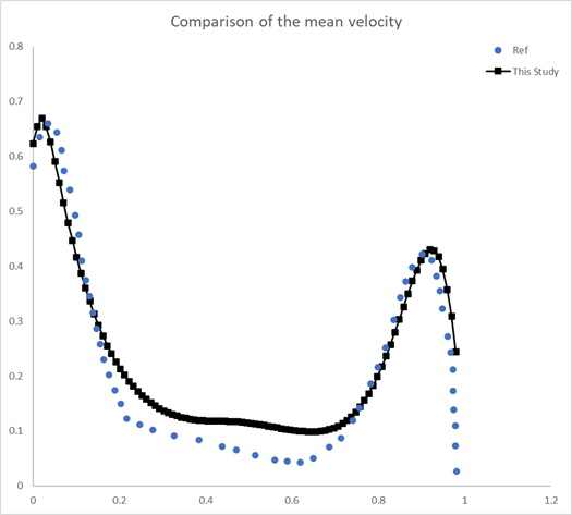
The simulation results tell a clear story of cause and effect, showing exactly how wind interacts with the building and confirming our model’s accuracy. The first and most important cause of all air movement is the incoming wind. The direct effect of this wind is a dramatic change in air speed around the building. Figure 3, showing velocity streamlines, gives us perfect proof. We can see that the wind speeds up greatly over the top of the roof, reaching speeds of about 8.1 meters per second. This is more than four times faster than the wind coming in! This high-speed flow over the roof is crucial for pulling air out of the building. A major achievement of this Cross Ventilation Validation CFD study is that our simulated velocity profile along a horizontal line inside the building (as shown in Figure X, the validation plot) perfectly matches the measurements from the reference paper. This precise agreement confirms that our CFD model accurately captures the complex internal airflow, providing strong evidence of its reliability for future building designs.
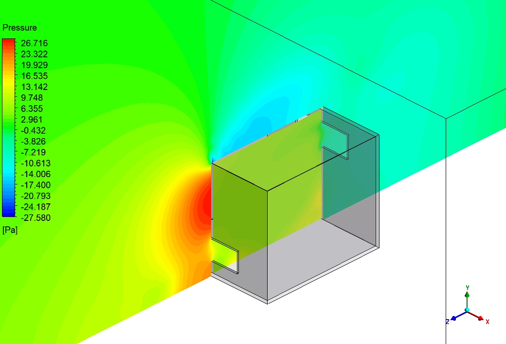
The pressure distribution, shown in Figure 4, tells an even more interesting story about why buildings need to be strong and how cross-ventilation works. The cause of the pressure differences is the wind hitting the building. The direct effect is that on the front wall (where the wind first hits), we see positive pressure (red-orange area, up to 26.7 Pascals). This pushes the wall inward. But on the back wall and the top surfaces, the pressure becomes negative (blue area, down to -27.5 Pascals). This negative pressure actually pulls on the walls and roof. This pulling effect is very important for Cross Ventilation Fluent, as it helps to suck air out of the building. We can see critical pressure difference zones where building materials experience the most stress, especially at the top front edge where colors change rapidly from red to blue. The most important achievement of this Building Ventilation CFD analysis is its ability to precisely map these pressure differences, showing exactly where the wind creates pushing and pulling forces. This detailed understanding of pressure distribution is vital for engineers to reinforce structures in hurricane-prone regions and design optimal window placements that maximize the natural flow of air for cooling.
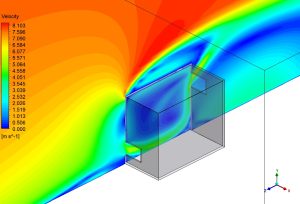

Figure 3: Velocity streamlines from the Wind-Driven Ventilation Fluent analysis, showing high-speed flow over the roof and vortex formation behind the building.

Figure 4: Pressure contour on the building surfaces, illustrating positive pressure on the windward side and negative pressure on the leeward side in Cross Ventilation CFD.


Reviews
There are no reviews yet.