


Entropy generation is a way to measure how much energy is wasted in a system. In any real process, like water flowing through a heated pipe, some energy is always lost and can no longer be used to do useful work. This happens for two main reasons: friction, as the fluid rubs against the pipe walls, and heat transfer, when heat moves from a hot area to a cold one. By calculating the Entropy Generation CFD, engineers can find the exact spots where a machine is inefficient. This helps them design better systems that save more energy. Our study aims to build a reliable CFD model to calculate this energy loss and prove it is correct by comparing it to a trusted research paper [1].
- Reference [1]: Sahin, Ahmet Z., and Rached Ben-Mansour. “Entropy generation in laminar fluid flow through a circular pipe.” Entropy5 (2003): 404-416.
Figure 1: Schematic of the heated pipe problem for Entropy Generation CFD Validation.
Simulation Process: Fluent Setup, Axisymmetric Modeling and UDF Implementation
To model the heated pipe, we used a smart shortcut. Because the pipe is perfectly round, we can simulate it using a 2D axisymmetric model instead of a full 3D one. This saves a lot of computer time. We created a high-quality structured grid to ensure our results are very accurate. The simulation in ANSYS Fluent was set up to solve for laminar fluid flow and heat transfer. The most important part was calculating the entropy. Since Fluent doesn’t have a built-in button for this, we wrote a User-Defined Function (UDF). This special code takes the simulation’s results for velocity and temperature and uses them to calculate the entropy generation at every point inside the pipe, based on the equations from the reference paper.
Post-processing: CFD Analysis, Validating Thermal and Frictional Energy Losses
Our simulation results show an almost perfect match with the data from the reference paper [1]. The validation table proves how accurately our Entropy Fluent model works. At the end of the pipe (axial location 1), the paper reported an entropy generation rate of 0.305, and our simulation calculated 0.303, which is an incredibly small error of only 0.66%. The agreement is excellent along the entire pipe, with errors at other points being 0.5%, 0.75%, and 0.68%. The only spot with a higher difference was 7.7% right at the entrance (location 0), which is normal because flow is always a bit unsettled as it enters a pipe. This comparison confirms that our CFD model is reliable.
Based on the given equations in the reference paper, the entropy generation rate can be calculated:
![\Phi = {2}\,\cdot\,\Biggl[ \Bigl(\frac{\partial v_{r}}{\partial r}\Bigr)^{2} \;+\; \Bigl(\frac{v_{r}}{r}\Bigr)^{2} \;+\; \Bigl(\frac{\partial v_{z}}{\partial z}\Bigr)^{2} \Biggr] + \Biggl(\frac{\partial v_{z}}{\partial r} + \frac{\partial v_{r}}{\partial z}\Biggr)^{2}](https://cfdland.com/wp-content/ql-cache/quicklatex.com-aa469bf37745fcf934f25e72615e1df3_l3.png "Rendered by QuickLaTeX.com")
![S_{\mathrm{gen}}^{\prime\prime} = \frac{k}{T^{2}} \Biggl[ \Bigl(\frac{\partial T}{\partial r}\Bigr)^{2} \;+\; \Bigl(\frac{\partial T}{\partial z}\Bigr)^{2} \Biggr] + \frac{\mu}{T}\,\Phi](https://cfdland.com/wp-content/ql-cache/quicklatex.com-2e4551694837a7490b703a3d6529d0ee_l3.png "Rendered by QuickLaTeX.com")
| Axial Location | Entropy Generation Rate (Paper) | Entropy Generation Rate (CFD simulation) | Error (%) |
| 0 | 0.013
0.183 0.269 0.291 0.305 |
0.014
0.182 0.267 0.289 0.303 |
7.7% |
| 0.1 | 0.5% | ||
| 0.5 | 0.75% | ||
| 0.75 | 0.68% | ||
| 1 | 0.66% |
The professional contour of the temperature provides a visual map of where one type of energy loss occurs. The fluid enters the pipe cold at 273.1K and gets much hotter, reaching 424.2K near the walls at the outlet. This large temperature difference between the wall and the fluid center is a major source of wasted energy, or thermal entropy. The other source of waste is friction, which happens where the fluid velocity changes quickly, especially near the pipe walls. The most important achievement of this simulation is the successful validation of a CFD model that accurately calculates the total entropy generation from both heat transfer and fluid friction. This provides engineers with a powerful and trustworthy tool to pinpoint and minimize energy losses, leading to the design of more efficient thermal systems.
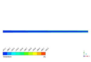
Figure 2: Temperature distribution from the Entropy Generation Heated pipe CFD simulation, showing fluid heating from 273.1K to 424.2K


Reviews
There are no reviews yet.