


In solid fuel combustion systems, erosive burning is a complicated process that speeds up the burning process when fast-moving gas flows across the fuel surface. An erosive burning process is different from other types of combustion because the moving gases have mechanical and heat effects which accelerate up the rate at which the solid fuel burns down. Advanced Computational Fluid Dynamics (CFD) simulation methods are needed to correctly study and guess such complex behavior. When dynamic mesh features are added to ANSYS Fluent, they let experts see how the shape of the solid fuel surface changes over time as it wears away and burns. User-Defined Functions (UDFs) are also very important for describing the physics of erosive burning because they let you make your own mathematical models of the burning rate, heat transfer, and surface regression. In our current journey, we have benefited from several reference papers including “Application of the Universal Expression for Erosive Burning to Nozzleless Solid Propellant Rocket Motors [1]”.
- Reference [1]: Özyörük, Yusuf, and Ali Can Özer. “Application of the universal expression for erosive burning to nozzleless solid propellant rocket motors.” 53rd AIAA/SAE/ASEE Joint Propulsion Conference. 2017.
- Reference [2]: Özer, Ali Can. Performance prediction of nozzleless solid propellant rocket motors. MS thesis. Middle East Technical University, 2015.
- Reference [3]: Krishnan, S., and Rajesh Ramakrishnan. “Effect of motor length and propellant formulation on nozzleless solid rocket performance.” Proceedings of the Institution of Mechanical Engineers, Part G: Journal of Aerospace Engineering1 (1999): 35-44.
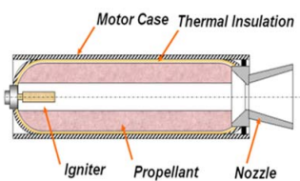
Figure 1: Solid fuel engine schematic
Simulation Process
The two-dimensional geometry was initially designed using Design modeler software, regarding the symmetric nature of motor to adopt Axisymmetric planar method later. The primary mesh grid is established with triangle elements. However, it is evident that the grid will be re-meshed by Dynamic Mesh module techniques including Smoothing and Remeshing methods as the motor wall starts deforming. Additionally, given the high-mach number flow inside the motor case, a Density-based solver is utilized to adopt compressibility effects. The implementation of our User-Defined Function (UDF) is based on the widely-adopted Erosive Burning Model, which expresses the propellant burn rate through the equation ![r=r_o+a(G^m-G_o^m)[U_g/c]^{0.5}](https://cfdland.com/wp-content/ql-cache/quicklatex.com-595cb33d57ab6d249377154f6dd30bae_l3.png "Rendered by QuickLaTeX.com") , where the parameters are calibrated for specific propellant characteristics. For non-aluminized HTPB propellants, the model utilizes specific constants including
, where the parameters are calibrated for specific propellant characteristics. For non-aluminized HTPB propellants, the model utilizes specific constants including  kg/s-m²,
  , and
, and  .
.
Post-processing
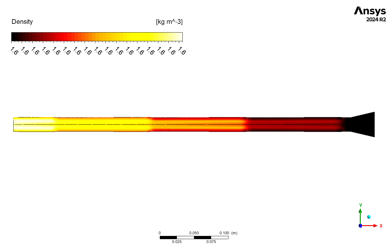
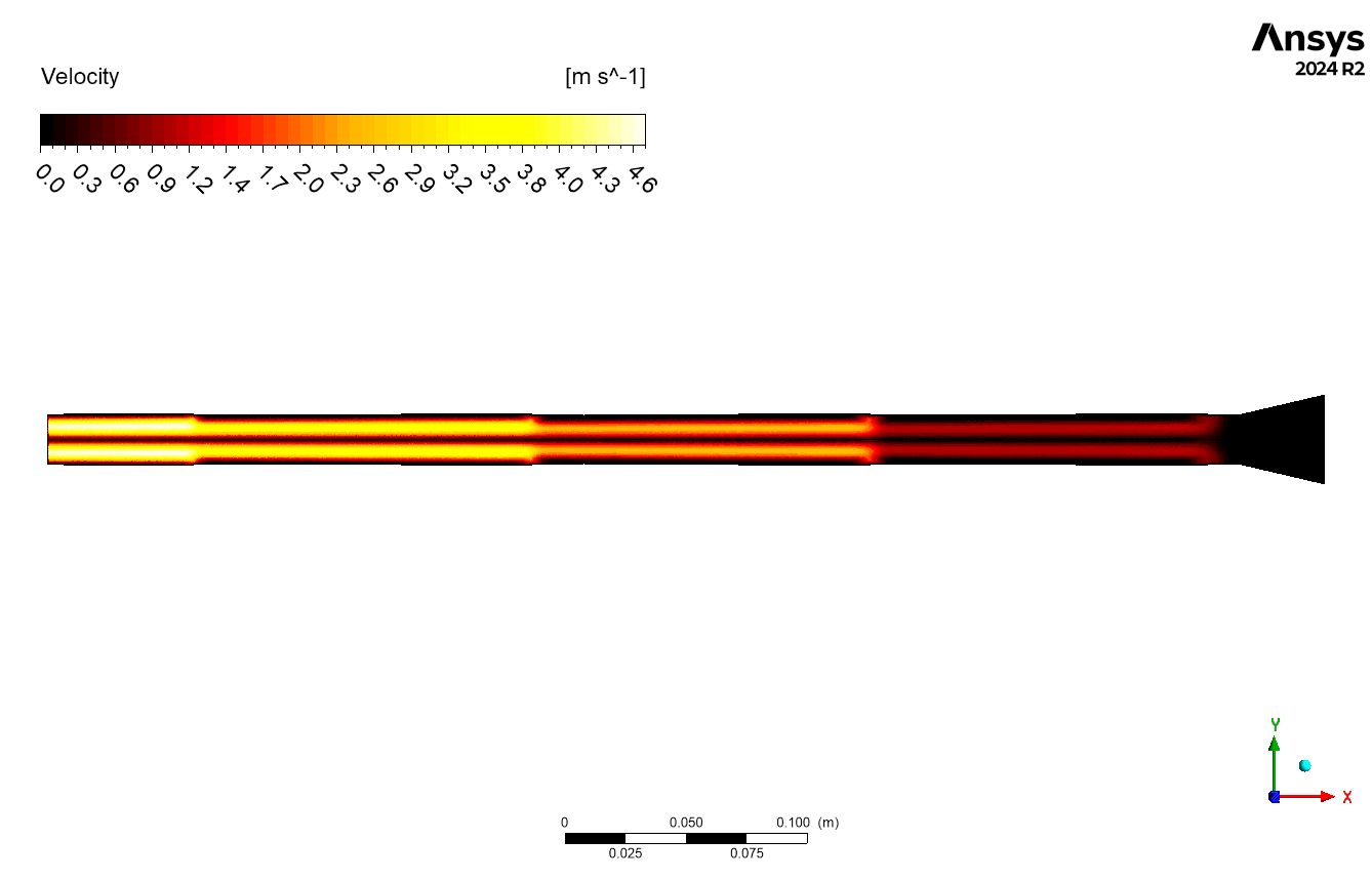
The CFD simulation findings showed clear patterns in the flow factors during the erosive combustion process. After examining the contours, we note that the density remains mostly constant at 1.6 kg/m³ for nearly all of the domain, with significant fluctuations occurring at the nozzle region where flow acceleration develops. The temperature distribution exhibits a gradual increase from 2403 K to 2414 K over the motor length, with peak temperatures localized in the nozzle region, where the flow experiences most compression. The velocity curves illustrate a gradual acceleration from 0 to 4.6 m/s, especially evident in the convergent section of the nozzle, aligning with the laws of mass and momentum conservation in compressible flow.
Figure 2: Density contour in Erosive Burning Using Dynamic Mesh & UDF CFD Simulation
The dynamic mesh implementation in ANSYS Fluent enables the capturing of the temporal evolution of these parameters as the solid fuel surface reduces because of erosive combustion. The UDF-controlled mesh movement precisely shows changes in shape, showing how the flow field adjusts to the changing motor configuration. This is especially apparent in the velocity and temperature profiles, where the interaction between the gas flow and the combustion surface generates unique boundary layer properties. The simulation findings clearly illustrate the relationship between flow parameters and the erosive burning rate
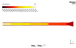
Figure 3: Temperature contour in Erosive Burning Using Dynamic Mesh & UDF CFD Simulation

Figure 4: Velocity contour in Erosive Burning Using Dynamic Mesh & UDF CFD Simulation


Reviews
There are no reviews yet.