


A heat press machine uses heat and pressure to put designs on items like t-shirts. A Heat Press Machine CFD simulation helps us understand how these machines work. This type of computer model is a heat transfer simulation that shows where the machine is hot and where it is cold. Using ANSYS Fluent, we can perform a thermal-structural analysis. This is very important because it shows how the heat changes the shape of the machine’s metal parts. This study uses a Fluent & Mechanical Coupling to see how the hot oil inside the press (fluid) affects the machine’s body (solid). This is a type of Fluid-Solid Interaction (FSI) that helps engineers build better machines that print perfectly every time.
The structural modelling figures out the thermal expansion, checks for stresses and strains, and looks at how the machine’s parts might change shape. Notably, the study is conducted based on a real industrial heat press machine.

Figure 1: The industrial heat press machine design used for this Fluent & Mechanical Coupling analysis
Simulation Process: Fluent & Mechanical Setup, One-Way FSI Coupling
To begin our simulation, we first created a 3D model of the heat press. We then used a meshing tool to create a very detailed grid with 5,582,908 cells. We put more cells near the pipes to get accurate results. The simulation is a one-way Fluid-Solid Interaction (FSI). This means we first solved how the hot oil heats the metal plates in ANSYS Fluent. Then, we took that heat data and used it in ANSYS Mechanical to see how the heat makes the machine bend and stretch. Because the strength of steel changes with temperature, we told the software that the material properties, like Young’s Modulus and Poisson’s Ratio, change as the machine gets hotter.
Figure 2: Temperature-dependent material properties defined for the Thermal-Structural Analysis.
Post-processing: CFD & FEA Analysis, Visualizing Thermal Stress and Deformation
The deformation contour shows the result of this uneven heating. This professional visual confirms that the top plate bends upwards in the middle, with the worst warping measured at 1.7486 millimeters. At the same time, the strongest parts of the frame barely move at all, with a minimum movement of just 0.011652 millimeters. This bending means the plate is no longer perfectly flat, so the pressure on the t-shirt is not even. The pressure is highest in the middle and lowest at the edges. This is why designs printed with real heat presses are often lighter or don’t stick well at the edges. The most important achievement of this simulation is proving with exact numbers how a 50°C temperature difference leads to a 1.75 mm warp, which directly causes uneven pressure and poor quality prints, giving engineers the precise data they need to redesign the heaters for a perfectly even result.
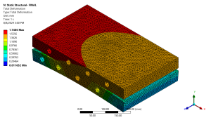
Figure 3: Total deformation analysis showing maximum bending of 1.7486 mm
The temperature contour gives us a professional visual of the heat distribution on the top plate. This professional visual shows that the middle of the plate gets very hot, reaching 176.97°C. However, the corners stay much cooler, at only 127.13°C. This is a large temperature difference of almost 50°C. This uneven heating is the main reason for problems. Because the middle is hotter, it tries to expand more than the cooler edges. This causes the entire plate to bend and warp.
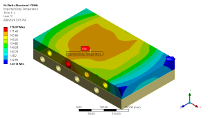
Figure 4: Temperature distribution from the Heat Press Machine CFD simulation, showing the hot center and cooler edges.


Reviews
There are no reviews yet.