


This report explores mixing layer simulation using computational fluid dynamics (CFD) with ANSYS Fluent. Mixing layers form when two fluid streams with different speeds flow side by side, creating a region where they mix together. These flow structures are really important in many engineering applications like scramjet engines for super-fast aircraft and supersonic ejectors used for pumping. This kind of CFD analysis helps engineers understand how fluid mixing happens and how to design better systems that use this mixing effect. Given the reference paper “ Experimental Study of Compressible Turbulent Mixing Layers”, the present numerical study is conducted to simulate the mixing layer phenomenon.
- Reference [1]: Goebel, Steven G., and J. Craig Dutton. “Experimental study of compressible turbulent mixing layers.” AIAA journal4 (1991): 538-546.
Figure 1: Schlieren photographs of mixing [1]
Simulation Process
Two separate inlets and an outlet inside a channel are designed using Design Modeler. 21600 structured cells are establishing the 2D domain. Despite the usage of water liquid in both inlets, the velocity gradient causes shear stress between two layers. However, both regimes remain within the laminar range.
Post-processing
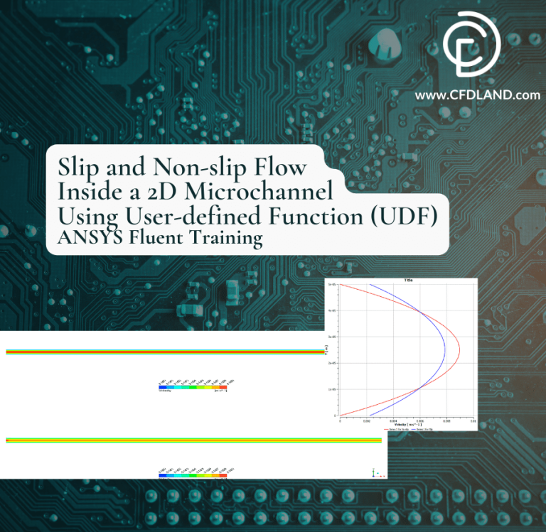
The velocity profile data shows a clear pattern of fully developed flow in our rectangular channel. Figure 1 shows the normalized mean streamwise velocity at 150mm downstream from the inlet. The profile has the classic parabolic shape that’s typical for laminar flow between parallel plates. Near the walls (at Y = 0mm and Y = 0.08mm), the velocity drops to zero because of the no-slip condition. The maximum velocity happens at the center of the channel (around Y = 0.04mm), reaching about 0.06 m/s. Interestingly, the profile is slightly asymmetric, with negative velocities on the left side of the graph showing some flow recirculation in that region.
Figure 2: Normalized mean streamwise velocity profile at 150mm from inlet, showing the characteristic parabolic shape of fully developed laminar flow
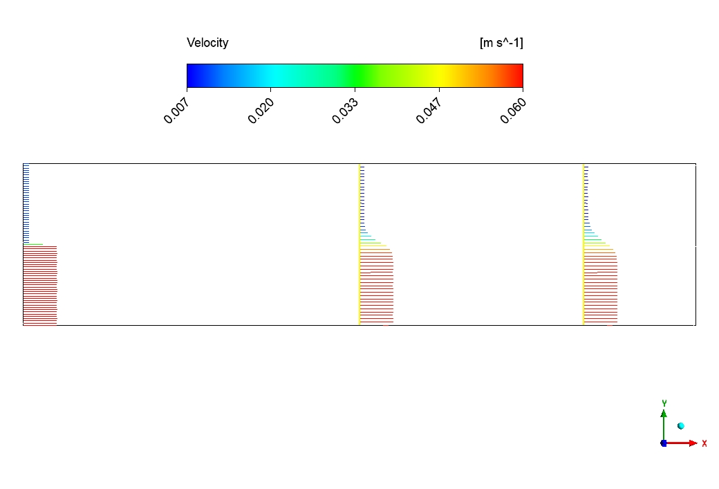
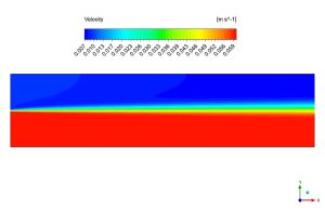
Figures 2 and 3 display the velocity contours in different views of the channel. In Figure 2, we can see the flow development along the channel with velocity vectors shown at three different cross-sections. The flow field starts to develop near the inlet (left side) and becomes more uniform as it moves downstream. The highest velocities (shown in red and orange) occur in the middle of the channel, while slower flow (blue) is near the walls due to friction. Figure 3 shows a side view of the velocity magnitude distribution. The thin green-yellow layer between the fast-moving center (red) and the stationary walls represents the boundary layer where the flow speed changes rapidly. This layer is very important for calculating drag forces and heat transfer. The even distribution of colors along the length of the channel confirms that we’ve achieved fully developed flow conditions, where the velocity profile doesn’t change anymore as the fluid moves downstream.
 624
624
Figure 3: Velocity vectors at three different cross-sections along the channel, showing flow development from inlet to outlet


Reviews
There are no reviews yet.