


A Pintle Ejector CFD simulation is a powerful computer model that helps engineers design better rocket engines and industrial sprays. This type of Spray Ejector CFD analysis is crucial for understanding liquid atomization, which is the process of breaking a liquid into very small droplets. Using ANSYS Fluent, we can study the complex two-phase flow of liquid and gas. A successful Pintle Ejector Fluent simulation allows us to see the spray breakup process, which is critical for achieving efficient combustion in a rocket engine injector. This work is based on two important reference papers, “Design Procedure of a Movable Pintle Injector for Liquid Rocket Engines” [1] and “LAGRANGIAN APPROACH TO AXISYMMETRIC SPRAY SIMULATION OF PINTLE INJECTOR” [2].
- Reference [1]: Son, Min, et al. “Design procedure of a movable pintle injector for liquid rocket engines.” Journal of Propulsion and Power4 (2017): 858-869.
- Reference [2]: Radhakrishnan, Kanmaniraja, et al. “Lagrangian approach to axisymmetric spray simulation of pintle injector for liquid rocket engines.” Atomization and Sprays5 (2018).
Figure 1: The working principle of a Spray In Pintle Ejector CFD system, based on the reference paper [1].
Simulation Process: Fluent Setup, Axisymmetric VOF Model for Spray Analysis
For this injector performance analysis, we used a 2D axisymmetric model. This smart choice simplifies the problem to save computer power but still gives us a full 3D understanding of the spray. We used ANSYS Design Modeler to create the geometry and a structured mesh to ensure the calculations are very accurate. The most important physics model for this simulation is the Volume of Fluid (VOF) method. We used an Eulerian-VOF model to precisely track the interface between the liquid and the gas. A key part of the design is the 0.8mm gas gap. This small gap forces the gas to move very fast, which is the main reason the liquid breaks apart.
Figure 2: The 2D axisymmetric domain and mesh used for the Volume of Fluid (VOF) Spray simulation.
Post-processing: CFD Analysis, Visualizing Spray Breakup and Atomization Dynamics
The volume fraction contour provides a professional visual that acts as a diagnostic tool for the atomization process. From an engineering perspective, this visual confirms that the injector is working as designed. We can see the liquid (shown in red with a volume fraction of 1.0) forming a thin sheet as it leaves the nozzle. The high-speed gas flowing through the outer gap creates a strong shear force on this liquid sheet. This force makes the sheet unstable and causes it to flap, similar to a flag in the wind. This flapping is the first step in the spray breakup process. The simulation shows the spray forms a cone shape with an angle of about 30 degrees, which is a key performance metric for ensuring the fuel spreads correctly inside a combustion chamber.
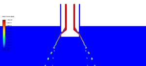
Figure 3: A professional visual of the liquid volume fraction from the Liquid Atomization CFD analysis, showing the complete breakup process.
This rocket engine injector CFD model allows us to analyze the entire breakup sequence. The initial liquid sheet, stretched thin by the fast gas, breaks into long threads of liquid called ligaments. These ligaments are also unstable and quickly break down further into the final tiny droplets. The contour shows the volume fraction of liquid dropping from 1.0 to less than 0.1 in a very short distance, which proves the injector is highly efficient at creating a fine mist. This is critically important because smaller droplets have a much larger total surface area, which allows them to mix with oxygen and burn much faster and more completely in a real engine. The most important achievement of this simulation is its ability to accurately capture the entire physics of atomization—from the initial liquid sheet instability to the final droplet formation—giving engineers a reliable tool to optimize injector geometry for maximum combustion efficiency and engine stability without building expensive physical prototypes.


Reviews
There are no reviews yet.