

Gas turbine inlet cooling through fogging systems represents one of the most effective power increase techniques for enhancing the performance of turbines like the LM2500 marine gas turbine. This widely used GE aero-derivative engine, delivering 18.6–22.4 MW of power, experiences significant performance degradation in hot conditions—approximately 5–10% power loss per 10°C rise in ambient temperature. Evaporative cooling simulation using the Discrete Phase Model (DPM) in ANSYS Fluent provides an advanced approach to optimize these systems through two-phase flow modeling. The fogging process works by injecting fine water droplets into the intake airflow, which evaporate and reduce the air temperature before it enters the compressor, resulting in denser air, increased mass flow rate, and thermal efficiency enhancement of 5–15%. Computational Fluid Dynamics (CFD) plays a crucial role in this optimization by accurately predicting droplet trajectories, evaporation rates, and resulting temperature profiles while minimizing risks of compressor blade erosion through precise Lagrangian particle tracking.
- Reference [1]: Chaker, Mustapha, and Thomas R. Mee III. “Design consideration of fogging and wet compression systems as function of gas turbine inlet duct configurations.” Turbo Expo: Power for Land, Sea, and Air. Vol. 56673. American Society of Mechanical Engineers, 2015.
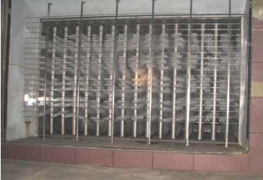
Figure 1: FOG NOZZLE MANIFOLD OPERATING IN THE INLET OF A GE-7EA GAS TURBINE [1]
Simulation Process
The 3-D domain of this simulation is based on the Marine Gas Turbine LM2500 Fogging Duct and has been designed using the ANSYS Design Modeler. It has an inlet and outlet. The meshing of this present model has been generated by ANSYS Meshing software. The mesh grid is unstructured, and the total cell number is 2492074 elements. The figure below shows an overview of the model. The Lagrangian-Eulerian framework is selected which means Discrete Phase Model (DPM) module is employed to track and solve DPM Droplets. Needless to say, the fogging system counts on water droplets evaporation after the injection. Thus, Species transport model is activated along the DPM.
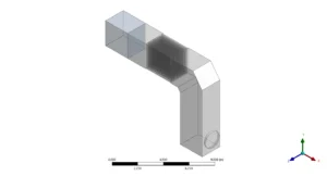
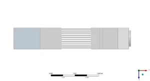
Figure 2: Geometric configuration of air intake turbine cooling system
Post-Process
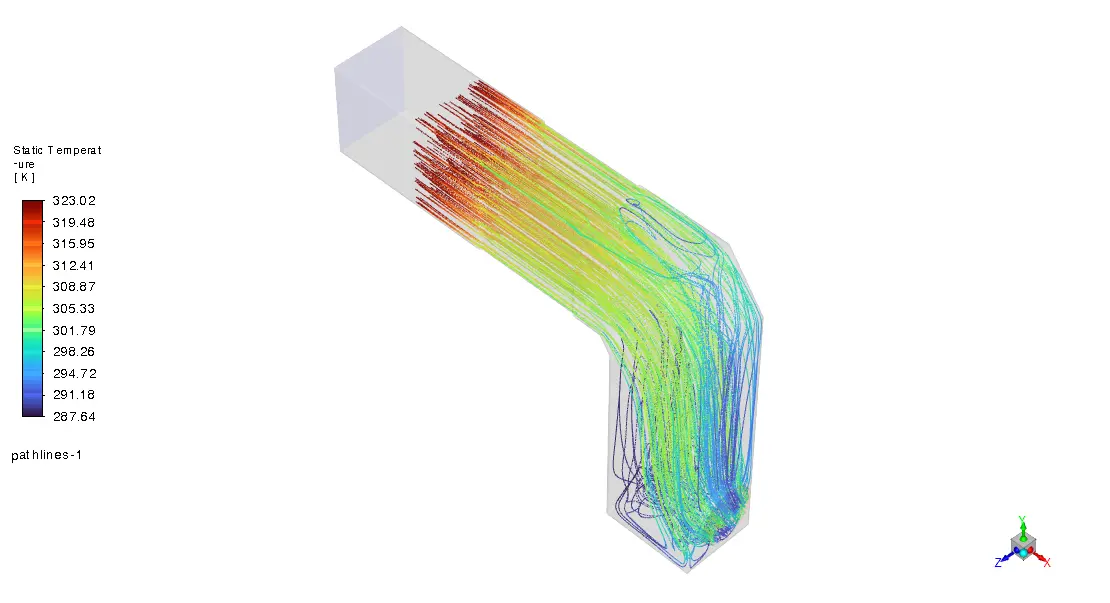
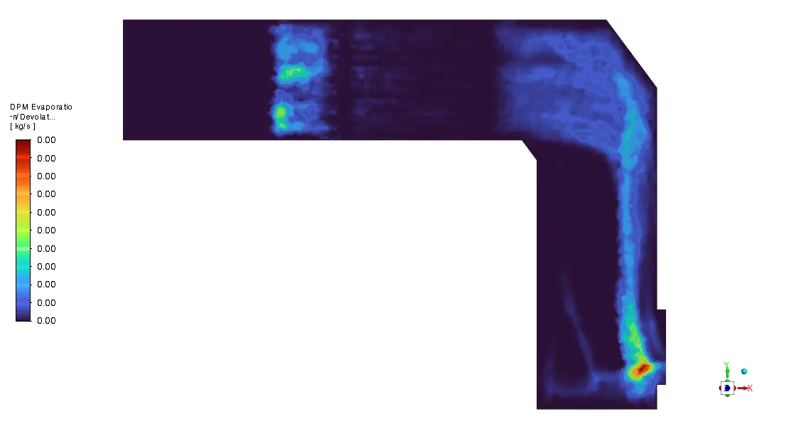
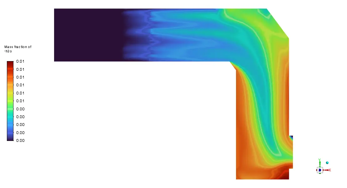
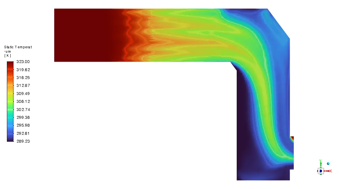
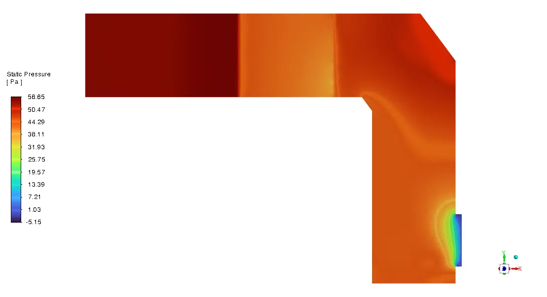
The temperature contour analysis shows that there is a lot of thermal stratification in the intake duct. There are hot spots (320–323K) near the intake that gradually change to cooler spots (289–295K) near the compressor opening. The amazing efficiency of the evaporative cooling process is shown by this temperature drop of about 30K. The complicated geometrical bend in the duct creates flow recirculation zones that help water droplets stay in place longer. This is shown by the higher evaporation rates seen in these areas of the second DPM contour picture. It’s interesting to see how much evaporation is happening along the outside wall of the bend, where centrifugal forces are pushing droplets around and creating cooling points where rates are highest in the red areas.


Figure 3: Temperature drop due to evaporative fogging system
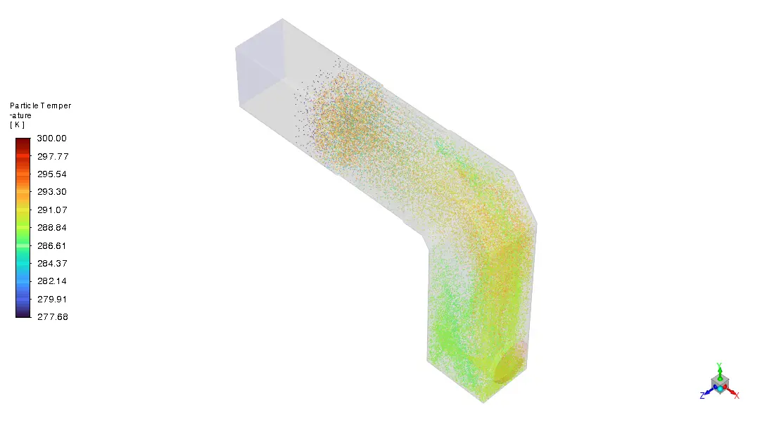
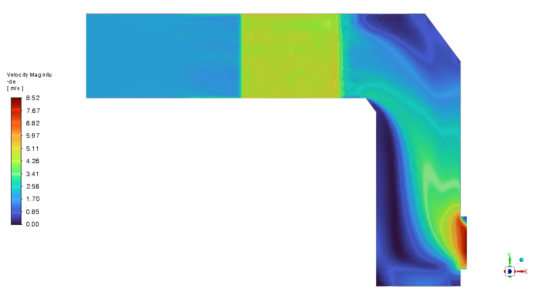
The streamline image shows that the droplets and turbulent flow are interacting in the best way possible, with pathlines showing that the temperatures drop gradually as they get closer to the compressor inlet. The 323K inlet flow (red streamlines) changes through temperature ranges in the middle (green, 305–310K) before reaching 290–295K (blue) at the exit, which means that almost all of the water has evaporated and the thermal efficiency has been improved. Based on the known link between inlet temperature and power output, this temperature profile optimization will directly lead to a roughly 12.5% power boost for the LM2500 turbine. Also, the fact that the temperatures are all the same at the outlet says that the mixing is very good, which is important for keeping the compressor blades from warping due to heat. This is a key part of making sure that the system works as planned and adding power. The results clearly show that the chosen nozzle design and DPM boundary conditions work well to get the best cooling performance.
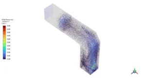
Figure 4: Droplets evaporation DPM CFD Simulation in turbine cooling system


Reviews
There are no reviews yet.