


In this UAV Propeller CFD Analysis tutorial, we provide a complete training guide on designing efficient drone blades. The propeller is the most critical component of any Unmanned Aerial Vehicle (UAV). It spins at high speeds to push air downward, generating the lift required for flight. Small changes in the blade twist or airfoil shape can significantly extend battery life or payload capacity. However, designing these blades is difficult because the tips move very fast, creating complex shock waves and turbulence. Real-world wind tunnel testing is expensive and risky. Therefore, engineers rely on CFD simulation to test designs virtually. In this ANSYS Fluent training, we use the MRF (Moving Reference Frame) technique to simulate the spinning motion. This Drone Propeller fluent simulation teaches you how to calculate thrust and torque accurately without needing a moving mesh.
In this lesson, we perform a detailed aerodynamic study. We examine the pressure distribution to understand how lift is generated and analyze the wake to identify energy losses. We also focus on calculating the dimensionless Thrust Coefficient (CT). For more training on rotating machinery, please explore our MRF CFD Simulation tutorials.
- Reference [1]: Ciattaglia, Gianluca, et al. “UAV propeller rotational speed measurement through FMCW radars.” Remote Sensing1 (2023): 270.
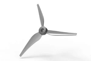
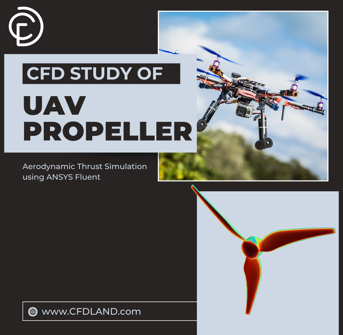
Figure 1: 3D Geometry of the UAV Propeller blade showing the twisted airfoil sections from the root to the tip used for this CFD simulation.
Simulation Process: MRF Setup in ANSYS Fluent
For this UAV Propeller CFD simulation, we created a cylindrical fluid domain that completely surrounds the blade. We divided this domain into two specific zones: an inner rotating zone containing the propeller and an outer stationary zone representing the far-field air. We generated a high-quality Polyhexa Unstructured Mesh. We added fine prism layers on the blade surface. This mesh refinement is essential to capture the boundary layer airflow, which dictates the drag forces.
We set up the physics using the MRF Fluent model. This method acts like a frozen rotor. It does not physically move the mesh grid but adds extra Centrifugal and Coriolis forces to the mathematical equations. We set the Rotational Speed to 50 RPM. We used standard air and solved the equations using the Steady-State solver in ANSYS Fluent. The solver iterated until the Thrust and Torque values became stable. This approach is highly efficient for predicting the performance of this ANSYS Fluent MRF case.
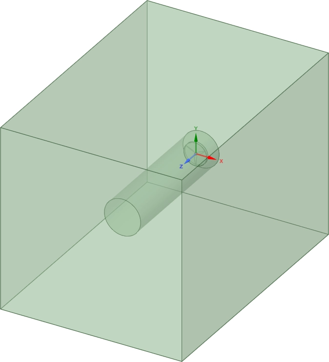
Figure 2: Computational Domain showing the inner rotating zone and the outer stationary zone used for the MRF Fluent setup.
Post-processing: UAV Propeller CFD Analysis of Thrust and Wake
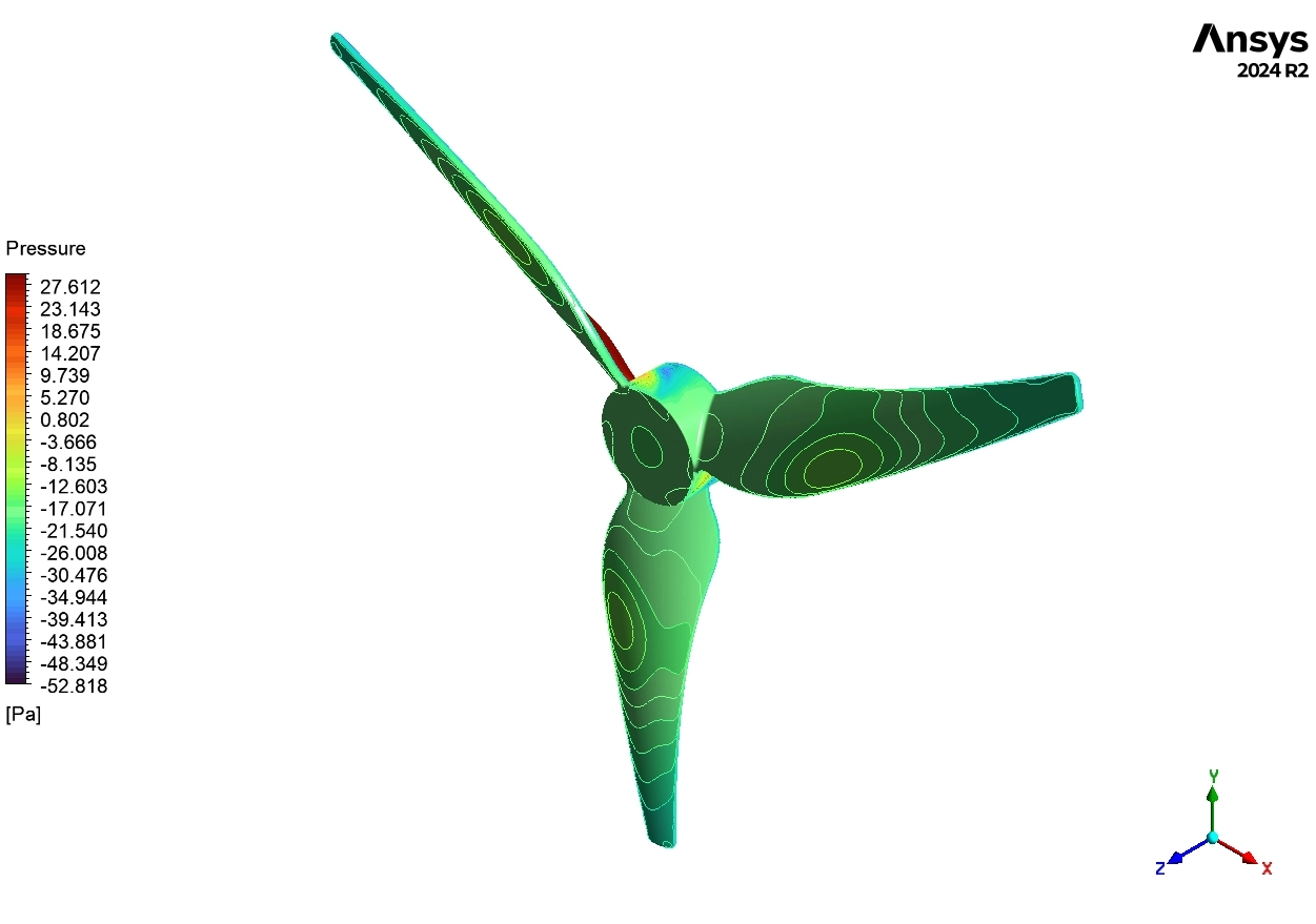
This section teaches you how to analyze the engineering data to evaluate propeller efficiency. We interpret the pressure and velocity contours to help you optimize the blade shape. First, we analyze the Static Pressure Distribution in Figure 3. The contours show a clear difference between the two sides of the blade. The bottom surface (Pressure Side) is Red, indicating High Pressure (+20 to +28 Pa). The top surface (Suction Side) is Blue, indicating Low Pressure (-53 to 0 Pa). Engineering Insight: This pressure difference is exactly what creates the Thrust Force. Notice that the lowest pressure (-53 Pa) is located near the leading edge. This means the suction on top contributes more to the lift than the push from the bottom. The gradient is smooth, which confirms that the airfoil shape is aerodynamically efficient.
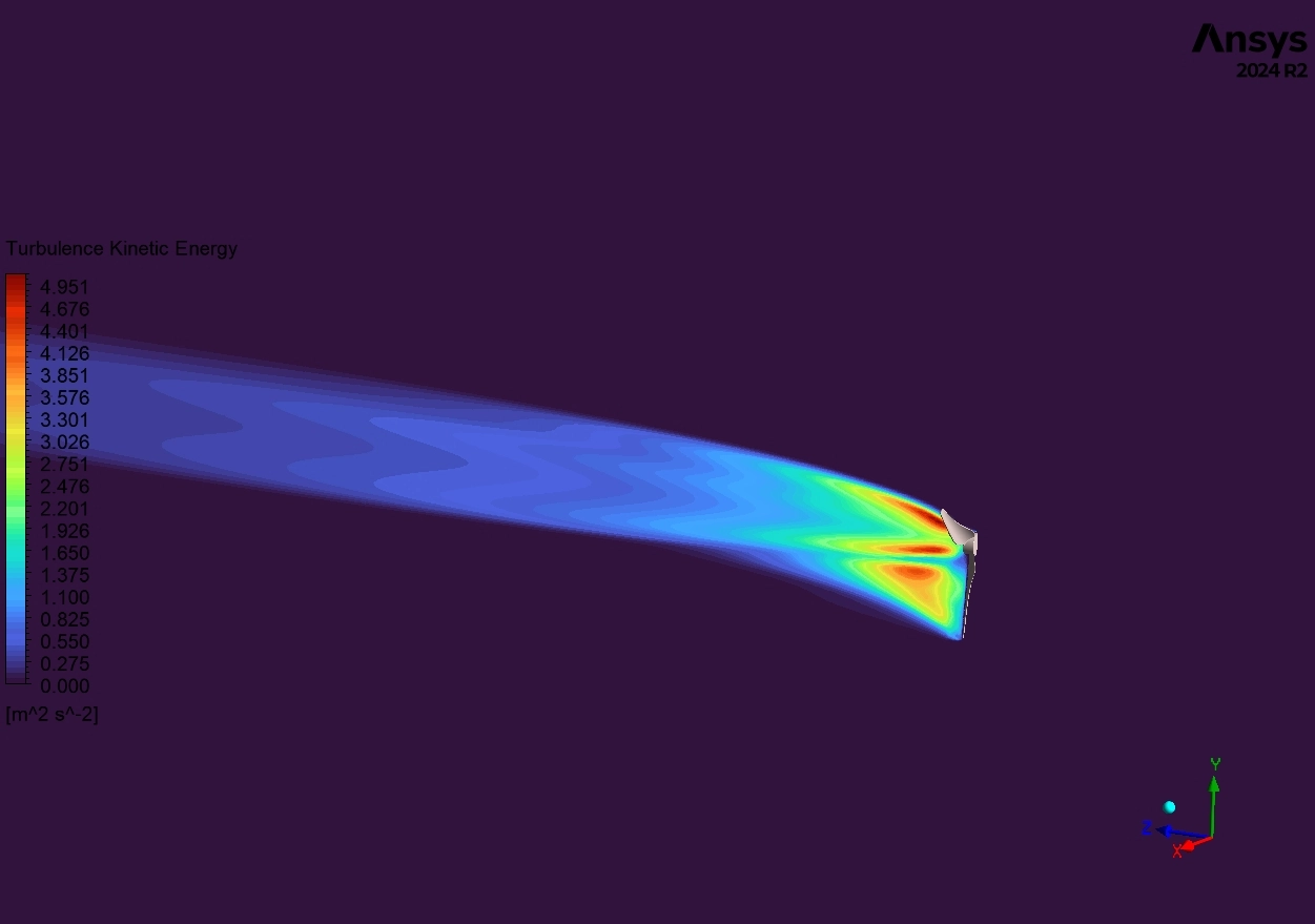
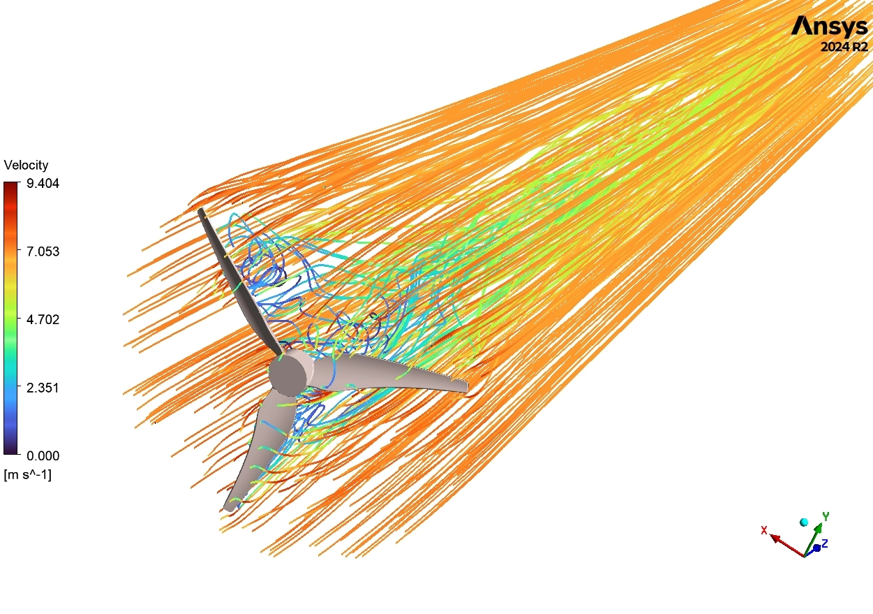
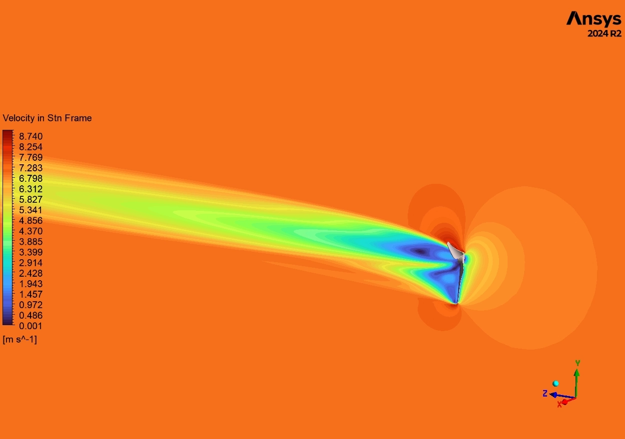
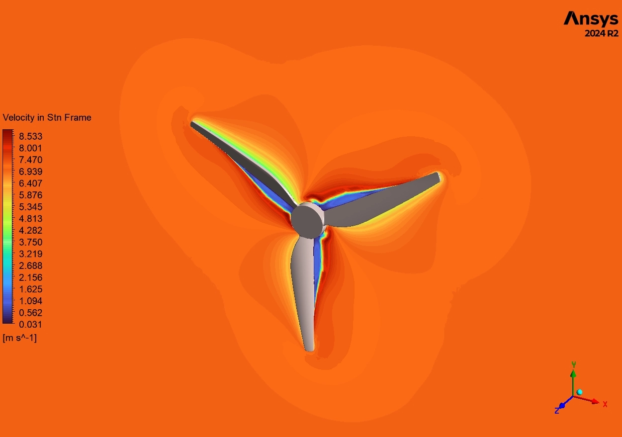
Next, we examine the Velocity Field in Figure 4 and Figure 5. The contours show the air velocity on the blade surface reaching 5-6 m/s. Since the physical tip speed at 50 RPM is only about 0.26 m/s, this high velocity proves that the propeller is effectively accelerating the air. The streamlines in Figure 5 show incoming air at 7-9 m/s converging through the disk. Behind the propeller, we see complex swirling patterns near the hub. These are Hub Vortices. Design Conclusion: These vortices represent leaked energy. A designer could improve this Drone propeller CFD model by redesigning the hub cap to smooth out this flow, which would reduce drag and noise.
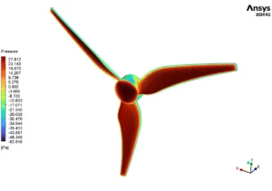
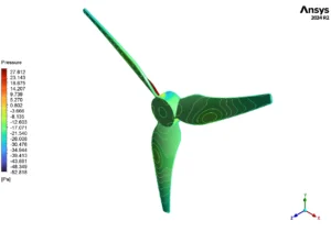
Figure 3: Pressure contours show pressure side at 0 to +28 Pa and suction side at -53 to 0 Pa, illustrating the lift generation mechanism.
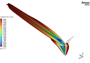
Figure 4: Velocity contours on blade surfaces reaching 5-6 m/s in the stationary frame, showing the acceleration of air over the airfoil.
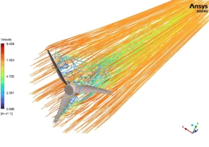
Figure 5: Streamlines show incoming flow at 7-9 m/s converging through the propeller
Finally, we calculate the quantitative performance in Table 1. Using the standard formula, we calculated a Thrust Coefficient (CT) of 0.002165. This dimensionless number allows manufacturers to compare this small propeller with much larger ones. The results confirm that the MRF Fluent method successfully captured the flow acceleration and force generation required for flight.
Table 1: Thrust coefficient calculation from UAV propeller CFD simulation in ANSYS Fluent at 50 RPM.
| Parameter | Symbol | Value | Units | Formula |
| Air Density | ρ | 1.225 | kg/m³ | Standard atmospheric |
| Rotation Speed | n | 50 | RPM | Operating condition |
| Rotation Speed | n | 0.833 | rev/s | n/60 |
| Propeller Diameter | D | 0.1 | m | Geometry specification |
| Thrust Coefficient | CT | 0.002165 | – | T / (ρn²D⁴) |


Reviews
There are no reviews yet.