
Modern factories use industrial lasers to cut and weld thick metals. These high-power machines create high thermal energy. If engineers do not remove this heat quickly, the internal optical lenses will lose focus. Eventually, the expensive equipment will melt. To stop this physical damage, designers use a Laser Head water cooling system. This closed loop pumps cold liquid around the hot parts to absorb the energy.
This report studies a real industrial model of laser and cooling system. We analyze the fluid dynamics to ensure the machine stays safe during continuous operation. You can study similar thermal management techniques in our heat transfer CFD simulation category. Also, to understand how these intense energy sources melt metals directly, please check our CFD Analysis of Laser-Arc Hybrid Welding project where we try to model real-time laser welding process.
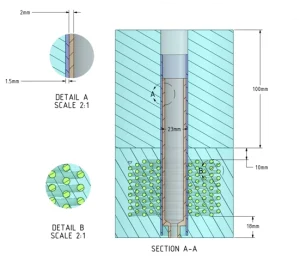
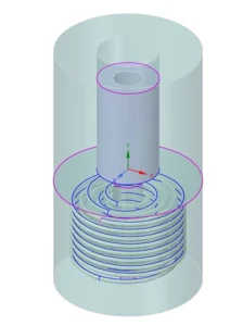
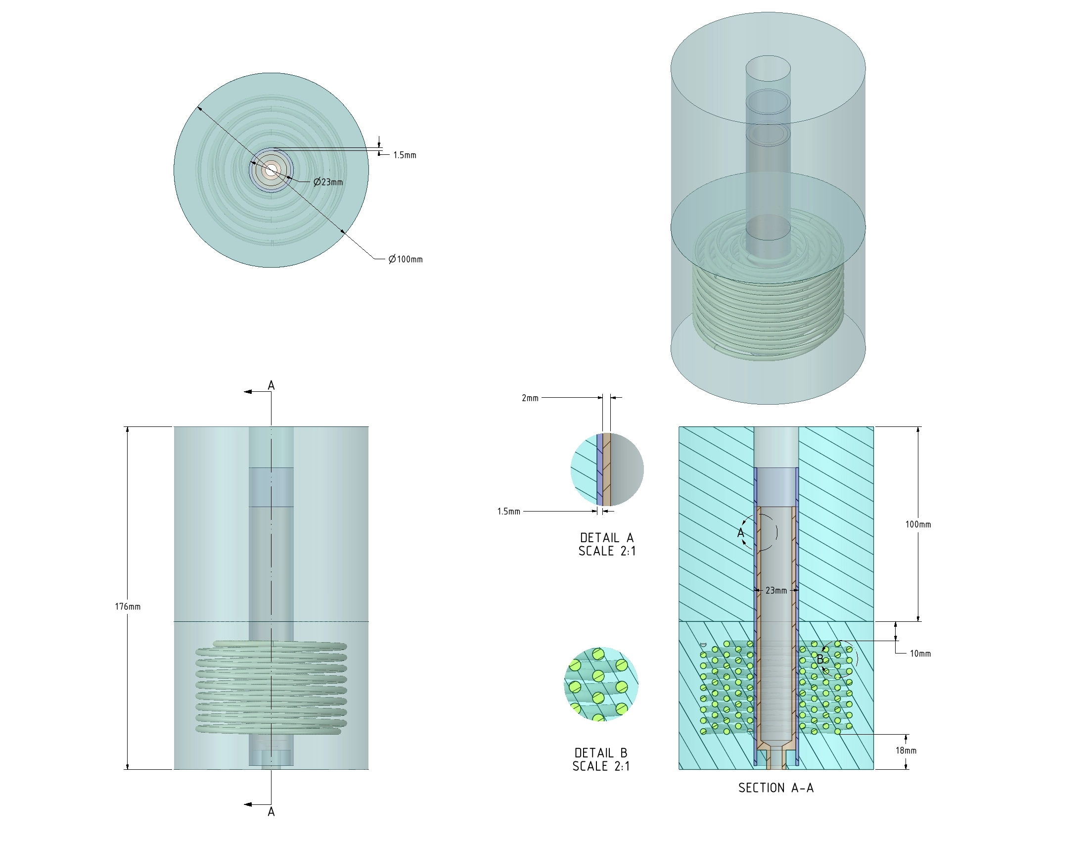
Figure 1: Structural schematic of the laser head geometry, showing the central cylindrical heater, the ceramic insulation, and the helical water cooling coil.
Simulation Process: Conjugate Heat Transfer Modeling
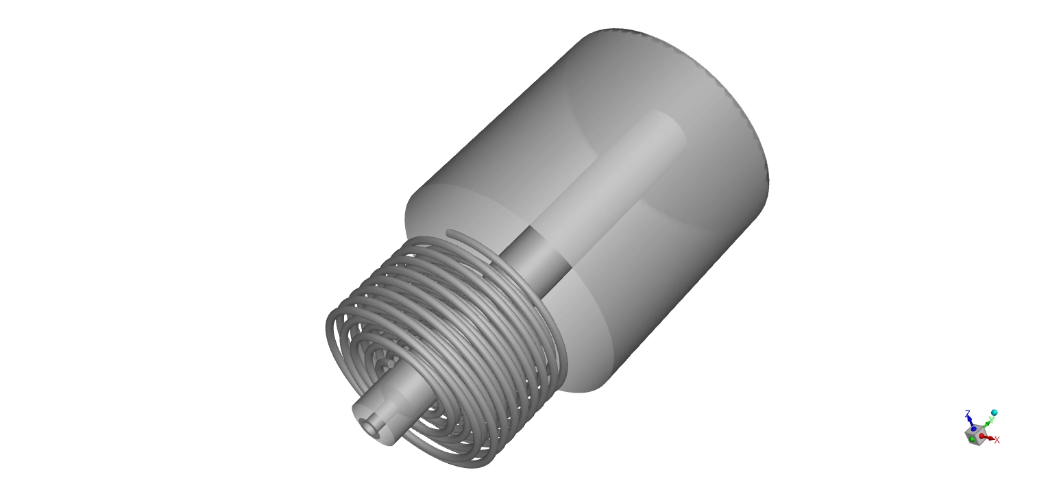
This industrial laser cooling system requires a complex 3D geometry. The physical parts include the central cylindrical heater, an Alumina ceramic insulation body, an optical nozzle, and a helical water cooling coil. To calculate the physics accurately, ANSYS Meshing divides the solid bodies and the fluid volume into 4,793,237 tetrahedral cells. These specific triangular cells adapt very well to the curved shape of the spiral pipe.
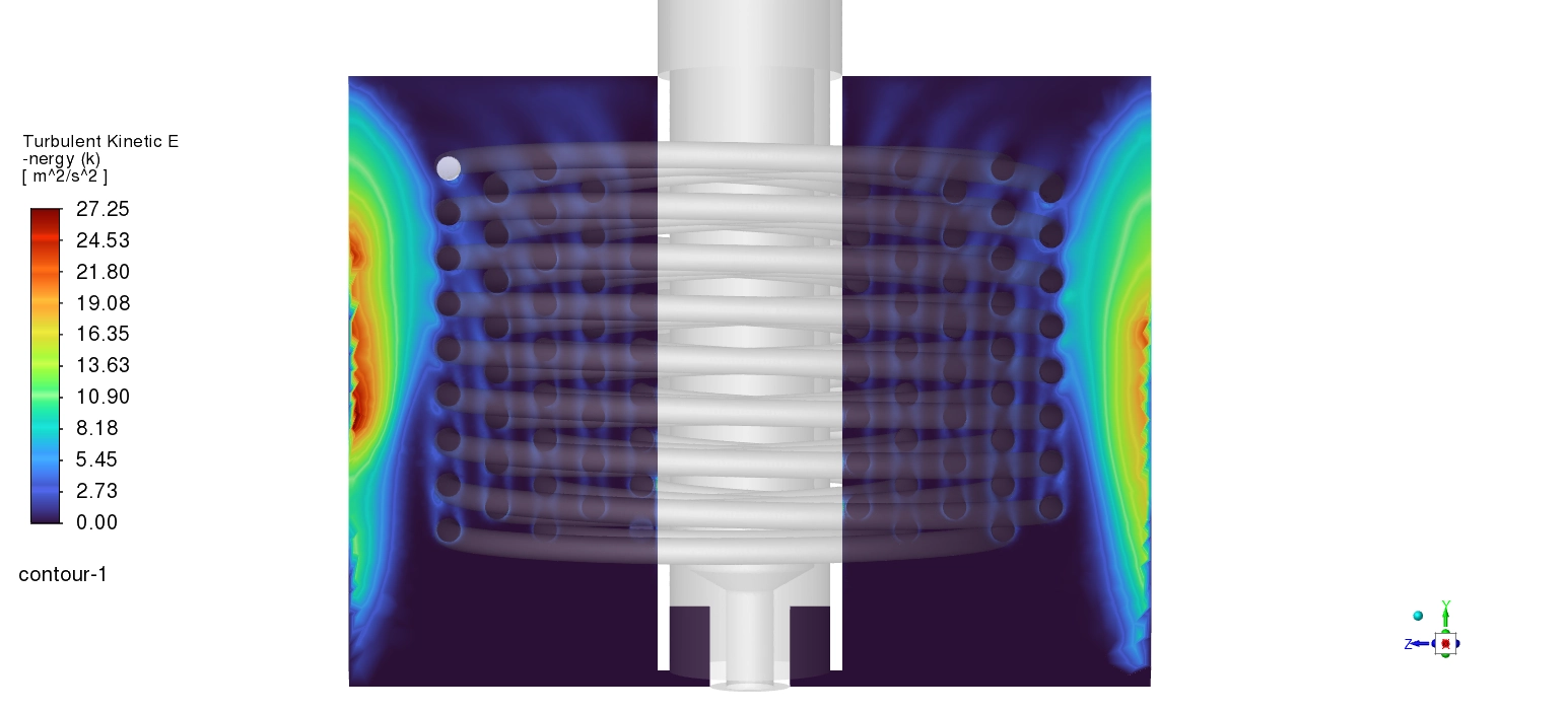
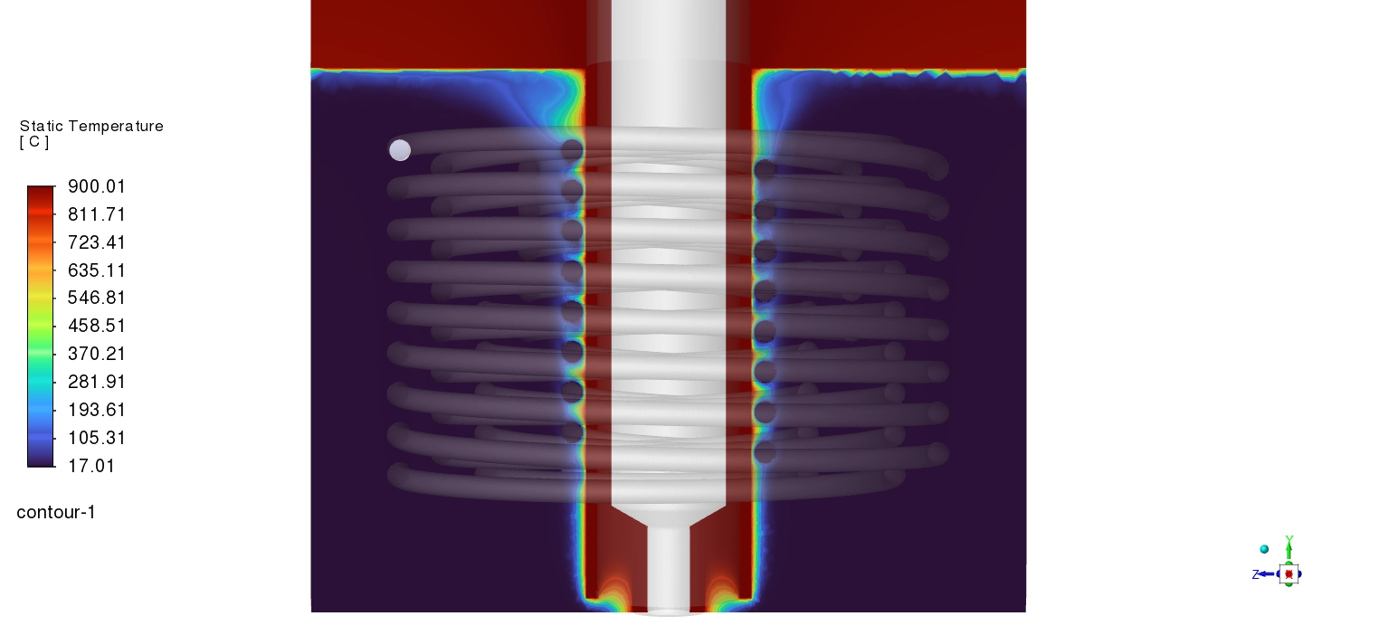
We consider conjugate heat transfer to study this machine properly. This physical method calculates the heat moving through the solid ceramic and the heat moving into the flowing water at the same time. We set the heat source to a fixed temperature of 900 °C. The cold liquid enters the coil at an inlet temperature of 17 °C. We push the water through the narrow tubes using a strict mass flow rate of 0.02 kg/s. Because the water moves quickly, the flow becomes highly turbulent.
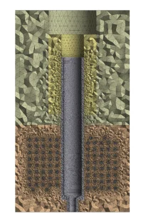
Figure 2: Computational representation featuring 4,793,237 tetrahedral cells, designed to resolve the fluid-solid boundary layers accurately.
Post-processing: Thermal Extraction and Dean Vortices
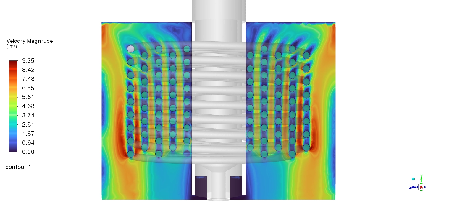
We analyze the velocity contours to understand how the fluid motion removes the heat. Inside the coiled pipe, the general water speed measures between 1.87 m/s and 4.68 m/s. However, as the water turns in a continuous spiral, strong centrifugal forces push the fluid against the outer curves of the tube. This physical action creates secondary flow patterns called Dean vortices. Because of this, the fluid speed accelerates to a peak velocity of 9.35 m/s at these outer bends. This high-speed turbulent mixing is very useful. It constantly breaks apart the thermal boundary layer, allowing cold water from the center to touch the hot walls faster.
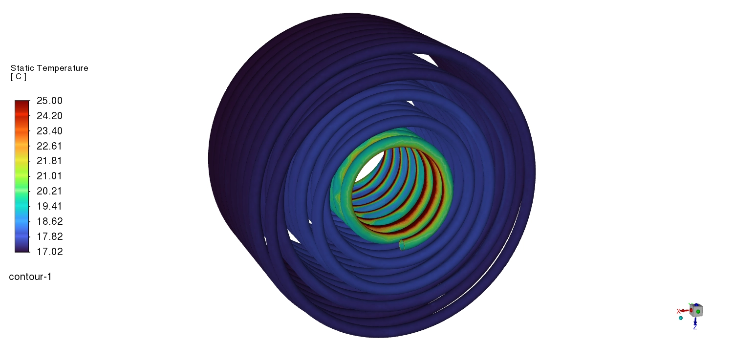
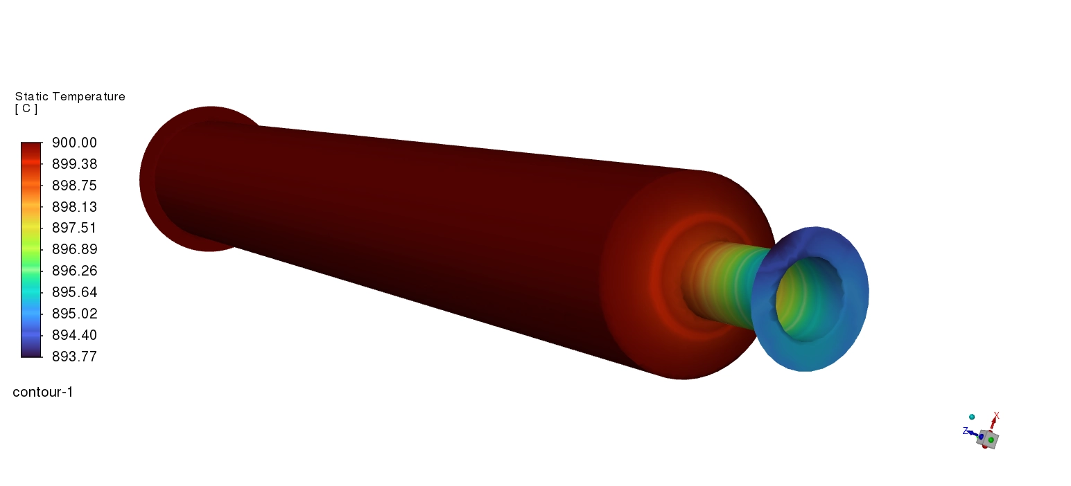
Then, we evaluate the thermal capacity. The cold water starts at 17 °C. As it absorbs the intense heat, the cross-sectional contours show the water slowly warming to 19 °C and 21 °C in the middle sections. The fluid exits the system with an average outlet temperature of 19.54 °C. By mathematically combining the 0.02 kg/s flow rate and the specific heat of water, we confirm a total temperature rise of 2.54 °C.
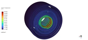
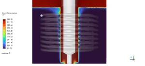
Figure 3: Static temperature distribution demonstrating the conjugate heat transfer from the 900 °C heater through the solid ceramic and into the cold water pipes.
Near the hottest contact zones, the local water temperature reaches a maximum of 25 °C. Because water boils at 100 °C, this system provides a strong safety margin. It completely prevents dangerous steam bubbles from forming inside the pipes.
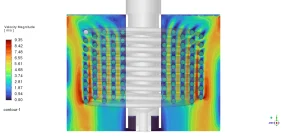
Figure 4: Velocity magnitude contours visualizing the turbulent acceleration up to 9.35 m/s caused by centrifugal flow patterns.
Frequently Asked Questions (FAQ)
- Why does the water speed increase at the bends of the coil? When fluid travels through a curved spiral pipe, centrifugal forces push the water outward. This creates secondary spinning flows known as Dean vortices, which increase the local speed to 9.35 m/s.
- Why is the 25 °C maximum water temperature important for safety? If the water becomes too hot, it will boil and create steam bubbles. Steam blocks the cooling process and damages the machine. A maximum temperature of 25 °C is safely below the 100 °C boiling point.







Reviews
There are no reviews yet.