

The nacelle is the brain of a wind turbine. It sits high on the tower and holds critical parts like the gearbox and generator. These machines work hard to create electricity, but they also produce a lot of waste heat. In fact, about 3% to 8% of the power turns into heat. If this heat stays inside, the parts can melt or catch fire. Engineers use Wind Turbine Nacelle CFD to predict these high temperatures before building the real turbine. We use ANSYS Fluent to calculate how heat moves by conduction, convection, and radiation inside the housing.
This simulation is complex because it involves air moving around very hot parts. Using CFD Analysis of Wind Turbine Nacelle, we can see if the ventilation system is strong enough. The Wind Turbine Nacelle Fluent simulation helps us design better cooling systems to keep the equipment safe in hot weather. It allows us to find exactly where the hot air gets trapped so we can fix it. For more details on thermal simulations, please explore our Heat Transfer tutorials.
- Reference [1]: Sen, Bhaswati, and Nabanita Datta. “Thermal Analysis of the Nacelle of a Small Horizontal Axis Wind Turbine Using a CFD Model in ANSYS-FLUENT.” Turbulence & Energy Laboratory Annual Conference. Cham: Springer Nature Switzerland, 2023.
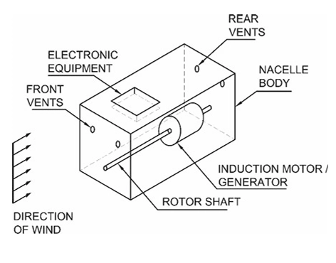
Figure 1: Schematic view of the nacelle geometry showing the placement of the gearbox and generator compartments inside the housing.
Simulation Process: Mesh Generation and Thermal Boundary Conditions in ANSYS Fluent
For this CFD Analysis of Wind Turbine Nacelle, we started by importing the 3D model of the nacelle geometry into the software. The model includes the large outer housing and the internal blocks for the generator and gearbox. We then generated the computational mesh using ANSYS Fluent Meshing. A high-quality mesh is essential to accurately calculate the heat transfer near the walls.
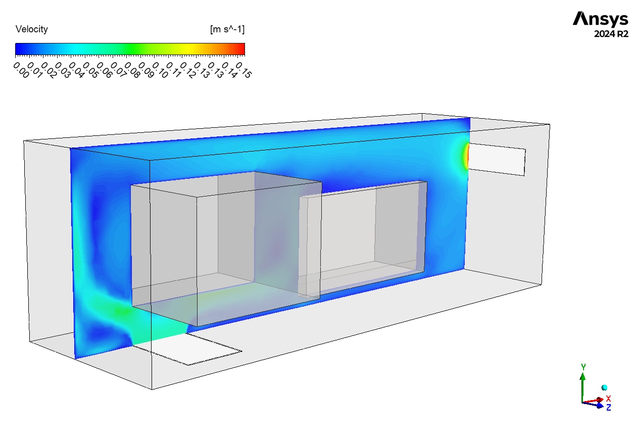
We set up the thermal physics and boundary conditions based on real operating data. We set the Generator Surface Temperature to 119°C to simulate full power operation. We set the Gearbox Surface Temperature to 70°C to account for heat from friction. To represent a harsh environment, we defined the Inlet Air Temperature at 38.5°C, simulating a hot summer day. This setup ensures the Wind Turbine Nacelle Fluent simulation captures all cooling effects, including how hot parts radiate heat to the cooler outer walls.
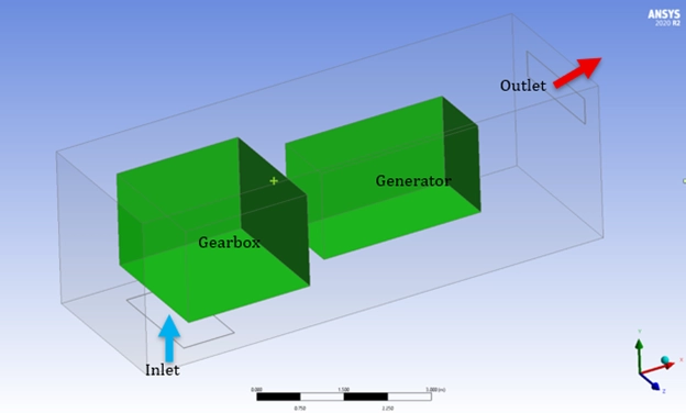
Figure 2: 3D Geometry Model prepared for the Wind Turbine Nacelle ANSYS Fluent simulation, including the transparent outer enclosure.
Post-processing: Thermal Analysis and Airflow Study of Wind Turbine Nacelle
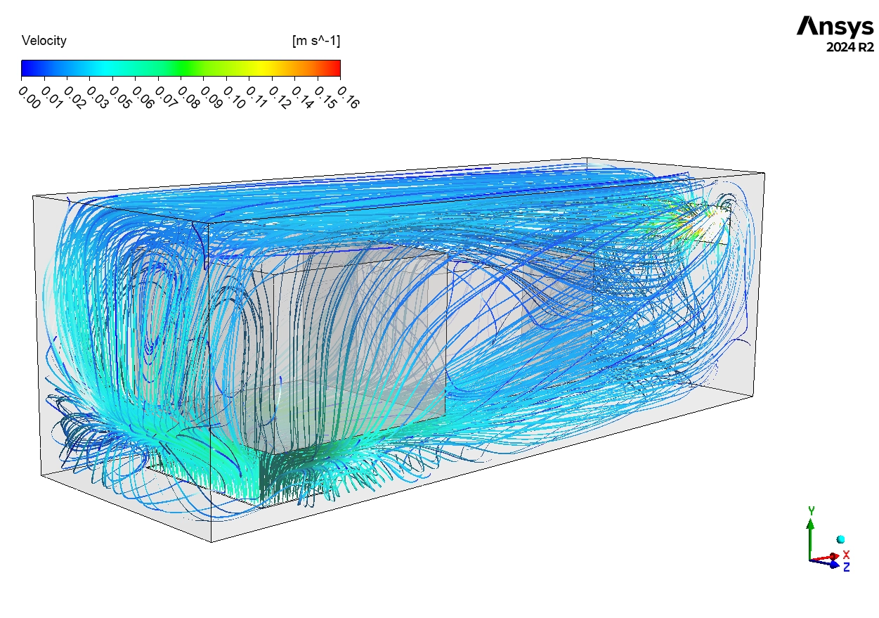
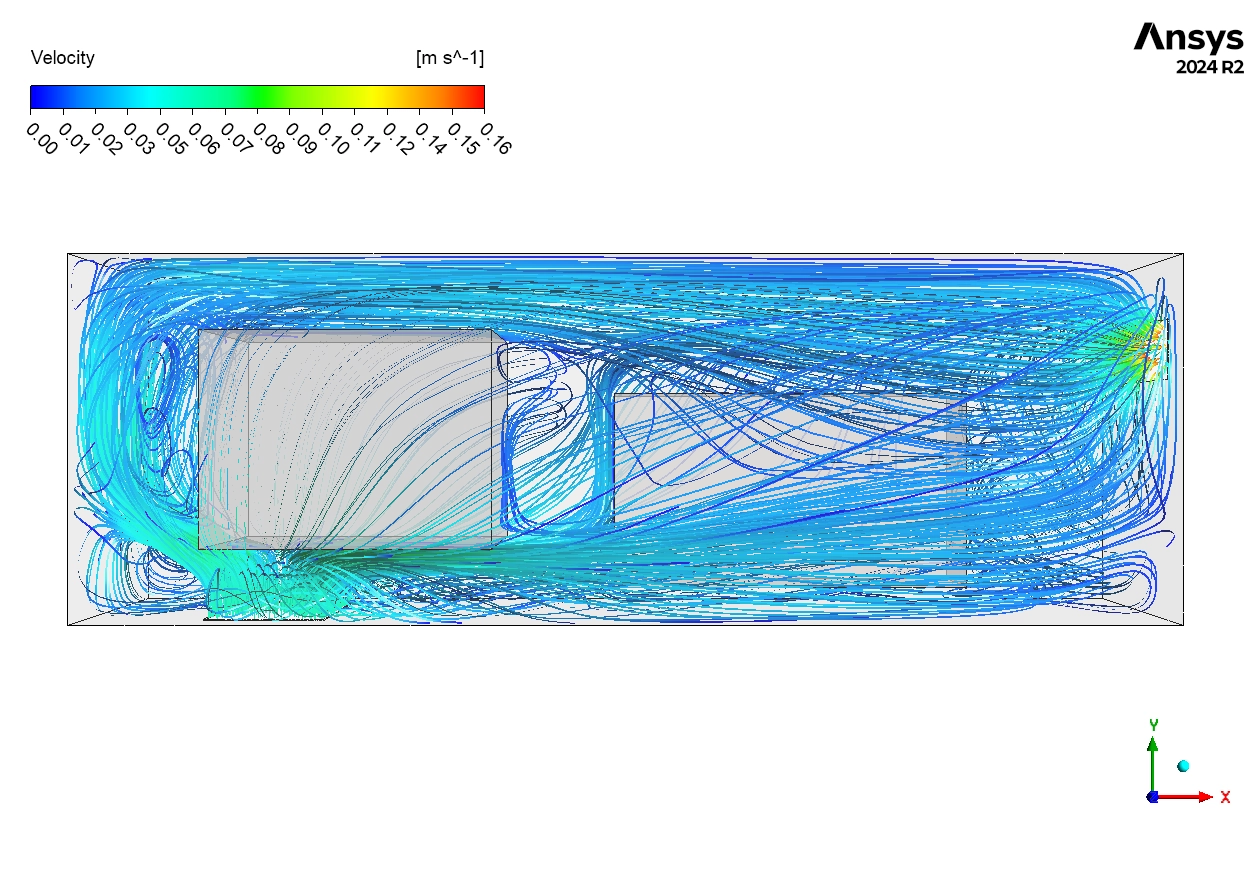
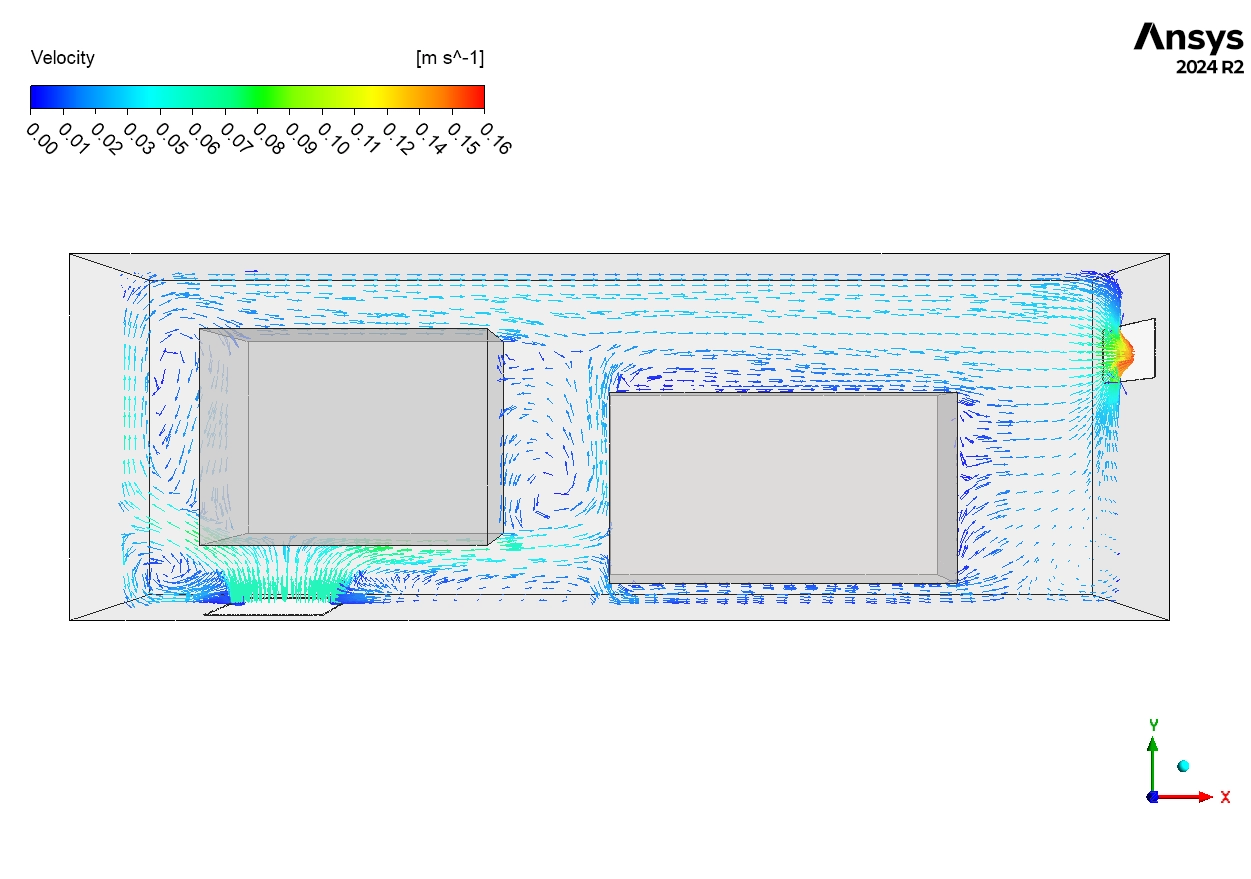
In this section, we provide a deep engineering analysis of the Wind Turbine Nacelle ANSYS Fluent results. We interpret the pathlines and temperature contours to evaluate the effectiveness of the cooling system for manufacturers. First, we analyze the Airflow Patterns shown in Figure 3. The pathlines show the air speed ranges from 0 m/s to 0.16 m/s. The engineering insight here is that the airflow is very uneven. The main stream of air, shown 0.05-0.10 m/s, flows along the top of the nacelle. It goes straight from the inlet to the outlet without deeply touching the hot components. This is a common design flaw called Bypassing. The air takes the easiest path and does not cool the machinery well. In the lower parts of the nacelle, we see Dark Blue Loops. These are Recirculation Zones where the velocity is near 0 m/s. The air here is stagnant. It does not move, so it cannot carry heat away efficiently.
Figure 3: Velocity vector inside the wind turbine nacelle showing airflow bypassing the hot components.
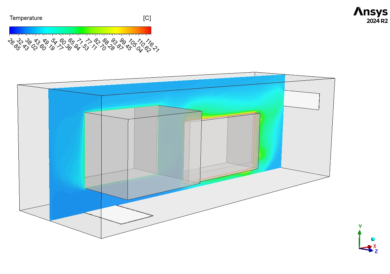
Next, we examine the Temperature Distribution in Figure 4. The contours confirm that the stagnant air causes severe overheating. The generator is the hottest part. The air right next to it is Red, reaching temperatures of 115-120°C. This reveals a Critical Thermal Issue. The air is only 4-5°C cooler than the generator surface itself (119°C). This proves that the convective cooling is very weak because the air velocity is too low. The Yellow-Orange zones (70-100°C) match exactly with the recirculation zones seen in the velocity plot. The heat accumulates here because fresh air does not flush it out. Even the cooler gearbox (70°C) creates a Thermal Plume, which is rising hot air that adds to the total heat load inside the enclosure. Finally, we can conclude that the current ventilation design is only Marginally Adequate. The generator temperature is dangerously close to the safety limit of 120-130°C. The Wind Turbine Nacelle CFD results show that relying on this simple airflow is risky. If the outside day gets slightly hotter or a fan breaks, the system will fail. To fix this, the manufacturer must add Baffles or Ducts to force the air down onto the generator. They should also increase the fan speed to eliminate the stagnant zones and lower the internal temperature below 100°C for guaranteed safety.

Figure 4: Temperature distribution in the wind turbine nacelle showing overheating zones near the generator.
Key Takeaways & FAQ
- Q: Why is the generator temperature so high?
- A: The airflow is “bypassing” the generator. The cool air stays at the top of the nacelle and does not mix well with the hot air at the bottom.
- Q: What is a “Thermal Plume”?
- A: It is a column of hot air that rises from a hot object (like the gearbox) because hot air is lighter than cold air.
- Q: How can we improve the design?
- A: We suggest adding Internal Ducts to direct the air straight onto the hot parts, or increasing the inlet fan power.


Reviews
There are no reviews yet.