
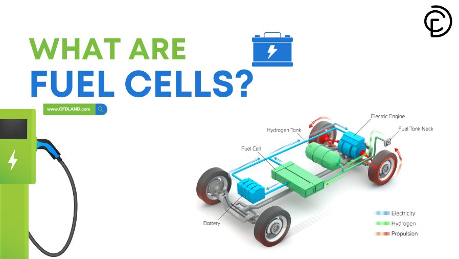
Fuel cells are cutting-edge electrochemical devices. They convert chemical energy directly into electrical energy. Unlike combustion-based systems, they offer high efficiency and very low emissions. Because of their global importance and rapid technological changes, even the US Department of Energy has focused extensively on fuel cells to create sustainable clean energy solutions.
This technical blog explores the foundation of these devices and focuses on fuel cell modeling. We explain how these systems are mathematically set up and solved. A complete overview of fuel cell CFD simulation in ANSYS Fluent is provided, covering both PEM fuel cell simulation and SOFC simulation. Engineers use these software settings to understand and optimize energy performance. For users who need practical files, advanced models and training tutorials are prepared in our major fuel cell and battery simulation tutorials library.
What are Fuel Cells? (The Foundation for Modeling)
A fuel cell is a device that generates electricity through a direct chemical reaction. This process occurs between a fuel, which is typically hydrogen, and an oxidizing agent like oxygen. This key reaction happens completely without combustion. Therefore, fuel cells operate quietly and very efficiently. In simple terms, it is a clean energy converter that powers everything from electric vehicles to large power plants. Because the internal physics are pretty complicated, CFD engineers rely on fuel cell modeling and electrochemical simulation to design them properly. Understanding these basic mechanisms is the first step before setting up a fuel cell simulation in engineering software.

Figure 1: A real prototype of a PEMFC – the image belongs to US department of energy website
How do Fuel Cells Work? (Understanding Physics before any simulation)
Figure 1 illustrates the working principle of a fuel cell. These chemical steps define the physical rules used in any electrochemical simulation. The process is broken down into the following key steps:
-
Hydrogen Fuel Input (Anode Side): As shown in the fuel cell diagram, hydrogen gas (H₂) is supplied to the anode side. The hydrogen interacts with a catalyst layer. Here, hydrogen molecules are split into protons (H⁺) and electrons (e⁻). This process is called electrochemical oxidation:
H₂ → 2H⁺ + 2e⁻
Then, the protons travel through the Proton Exchange Membrane (PEM) toward the cathode side.
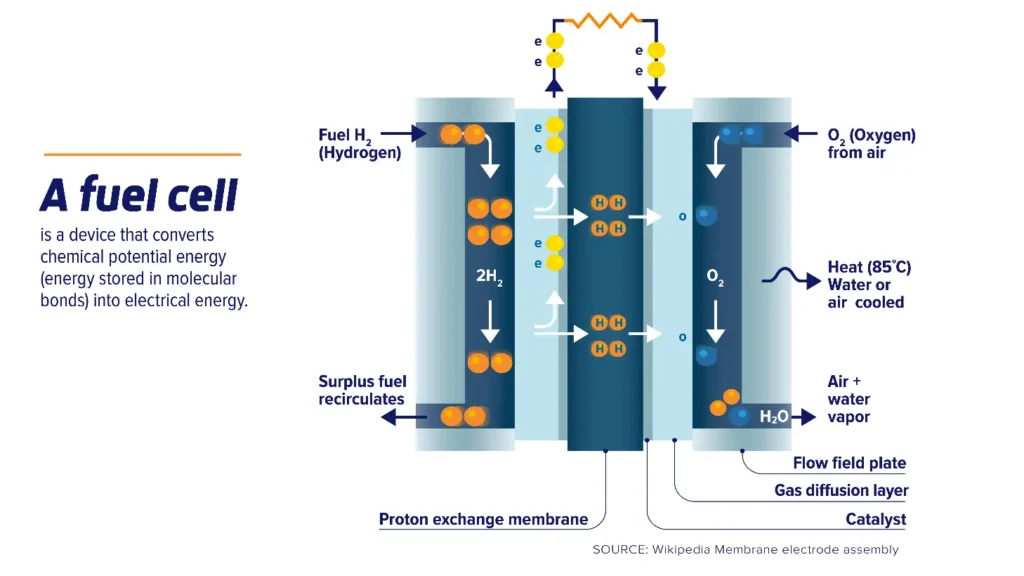
Figure 2- Schematic Representation of Proton Exchange Membrane Fuel Cell (PEMFC) Working Principle [1]
2. Electron Flow (External Circuit): As depicted in the diagram, electrons cannot pass through the membrane. Instead, they flow through an external circuit. This movement generates an electric current. In an ANSYS Fluent setup, this electron flow relates directly to the calculated current density.
3. Oxygen Input (Cathode Side): Oxygen gas (O₂) is fed to the cathode side. Software models calculate this process as species transport. At the cathode, oxygen reacts with the protons and the incoming electrons. This reaction forms water (H₂O) as a byproduct:
O₂ + 4H⁺ + 4e⁻ → 2H₂O
4. Heat and Water Production: The electrochemical reaction produces heat and water vapor as byproducts. Excess heat is managed through air or water cooling systems. In advanced modeling, engineers often simulate a fuel cell heat exchanger to study thermal management. Proper water management must also be simulated so the system does not fail. The net reaction is:
H₂ + O₂ → H₂O + Electricity + Heat.
Key Components for Modeling: In technical setups, these inner parts are physically grouped and modeled as the Membrane Electrode Assembly (MEA).
- Proton Exchange Membrane (PEM): A thin, permeable layer. It allows protons to pass while it blocks electrons.
- Catalyst Layer: This layer facilitates the chemical reactions at both the anode and the cathode.
- Gas Diffusion Layer (GDL) & Flow Field Plate: These parts ensure the uniform distribution of gases. They also aid in the removal of water. Defining the GDL correctly is highly important for accurate CFD results.
Types of Fuel Cells
There are several types of fuel cells, each designed for different industrial uses. Because they produce clean energy without harmful gases, scientists constantly work to improve their designs through advanced fuel cell modeling. According to Table 1, different types of fuel can be used to drive these systems. Pure hydrogen is commonly used by low-temperature devices, such as the alkaline fuel cell (AFC) and polymer electrolyte membrane fuel cell (PEMFC). This pure hydrogen can be produced from hydrocarbons, methanol, or syngas. High-temperature types, such as the molten carbonate fuel cell (MCFC) and solid oxide fuel cell (SOFC), are more flexible with their fuel sources. In engineering software like ANSYS Fluent, the PEM fuel cell simulation and the solid oxide fuel cell simulation are the two most widely used mathematical models.
Table 1- Comparison between different type of fuel cell [2]
| Fuel Cell Type | PEMFC | AFC | DMFC | PAFC | MCFC | SOFC |
| Operating temp (°C) | 30–100 | 90–100 | 50–100 | 160–220 | 600–700 | 500–1000 |
| Electrical efficiency (%) | 30–40 | 60 | 20–25 | 40–42 | 43–47 | 50–60 |
| Energy conversion efficiency (%) | 85–90 | 85 | 85 | 85–90 | 85 | up to 90 |
| Typical stack size | <1–100 kW | 10–100 kW | Up to 1.5 kW | 50–1000 kW (250 kW module typical) | <1–1000 kW (250 kW module typical) | 5–3000 kW |
| Electrolyte | Solid polymeric membrane | Aqueous solution of potassium hydroxide soaked in a matrix | Solid organic polymer poly-perfluoro sulfonic acid | 100% phosphoric acid stabilized in an alumina-based matrix | Li2CO3/K2CO3 materials stabilized in an alumina-based matrix | Solid, stabilized zirconia ceramic matrix with free oxide ions |
| Fuels | Hydrocarbons or methanol | Pure hydrogen | Methanol | Hydrogen from natural gas | Natural gas, biogas, others | Natural gas or propane, hydrocarbons or methanol |
| Operational life cycle | 40,000–50,000 h | Up to 5000 h | 10,000–20,000 h | Up to 40,000 h | Up to 15,000 h | Up to 40,000 h |
Fuel cells have many commercial applications. Figure 3 shows the power-delivering capability of various fuel cell uses.
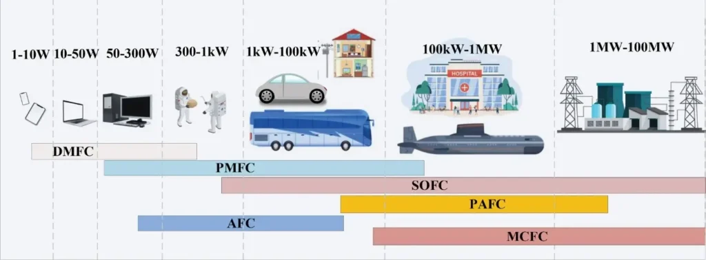
Figure 3- Power levels of portable and stationary Fuel Cells uses [3]
Figure 4 also compares different types of fuel cells based on their electrolytes, operating temperatures, and ion transfer mechanisms between the anode and the cathode. Understanding these physical differences is essential for defining accurate boundary conditions when setting up any electrochemical simulation.
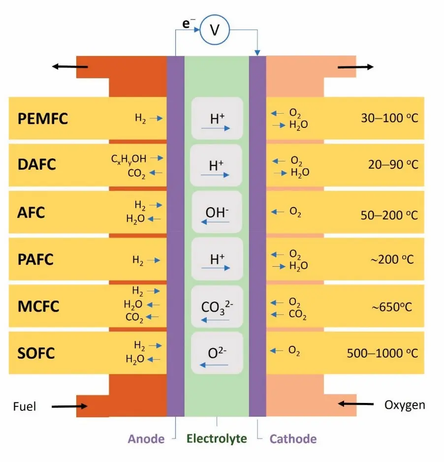
Figure 4- Classification of Fuel Cells examples based on the fuel and electrolyte [4]
Fuel Cells vs Batteries
Understanding the differences between fuel cells and batteries (Fig. 5) is key to evaluating which technology suits a specific application. While a battery is an energy storage device, a fuel cell is an energy conversion device. Although both systems use electrochemical reactions to generate electricity, their operation, efficiency, and modeling physics vastly differ.
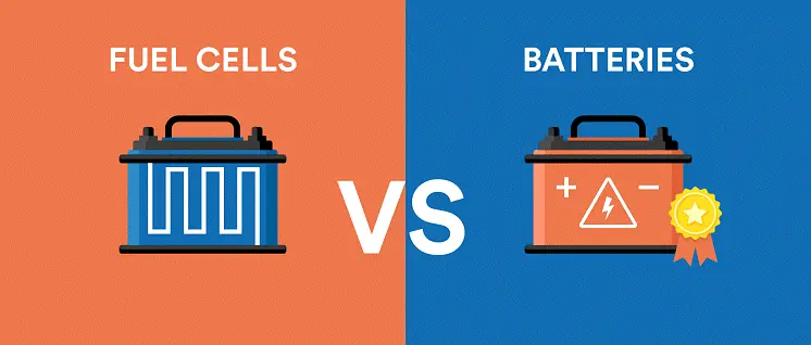
Figure 5- Fuel Cells vs Batteries
Batteries
- Store a finite amount of energy chemically inside their electrodes and release it through redox reactions.
- Require longer recharging times once the internal reactants are depleted.
- Have limited energy capacity based on their physical size.
- Common in portable electronics, standard electric vehicles, and backup power systems.
Fuel Cells
- Continuously produce electricity as long as an external fuel (e.g., hydrogen) and oxidant are supplied.
- Do not need recharging. they are quickly refueled in minutes.
- Offer higher energy density, making them ideal for heavy-duty transport and long-duration energy needs.
- Ideal for hydrogen fuel cell cars, industrial applications, and clean power plants.
Figure 6 showcases a fuel cell stack. This is a collection of individual fuel cells assembled together to generate higher electrical power. Each cell within the stack contains an anode, a cathode, and an electrolyte. They work together to convert chemical energy from hydrogen and oxygen into electricity. The metallic design indicates durability and precision engineering. The visible connectors and gauges suggest complex balance-of-plant components (like pumps and compressors) that manage the fuel supply. Because managing heat and gas distribution across many layers is highly complex, engineers rely on advanced fuel cell stack simulation to optimize these large power units before they are physically built.
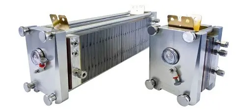
Figure 6-A Fuel Cell Stack
Hydrogen Fuel Cell Cars: How it Works
Hydrogen fuel cell cars (Fig. 7) use fuel cells to generate electricity through an electrochemical reaction between hydrogen (stored in high-pressure tanks) and oxygen from the air. This produces electricity to power the electric motor, with water and heat as the only byproducts. To design these advanced vehicles safely, automotive engineers rely heavily on PEM fuel cell simulation.
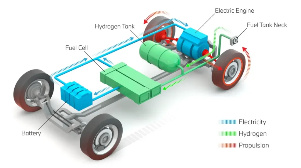
Figure 7- The Schematic of Hydrogen Fuel Cell Cars
Here is a breakdown of how hydrogen fuel cell cars work:
- Hydrogen Storage: Compressed hydrogen is stored in pressurized tanks within the car.
- Fuel Cell Stack: This is the heart of the system. Engineers use the Fuel Cell and Electrolysis Model in software to simulate how hydrogen reacts with oxygen here.
- Electrochemical Reaction: Hydrogen molecules are split into protons and electrons at the anode. Protons pass through the electrolyte to the cathode. The electrons travel through an external circuit, generating electricity to power the motor.
- Oxygen Supply: Oxygen from the air is fed to the cathode to combine with the protons and electrons, forming water as the only emission. Software calculates this as species transport.
- Electric Motor: The electricity generated by the stack drives the motor, propelling the car forward.
Hydrogen fuel cells advantages include zero emissions (only water vapor), fast refueling, and long driving range. These, making hydrogen fuel cell cars a promising alternative to, where Hydrogen fuel cell efficiency is higher than battery electric vehicles.
Fuel Cell Simulation in ANSYS Fluent
At CFDLAND, we dedicated a strong attention to fuel cell simulation in ANSYS Fluent. ANSYS Fluent provides a specialized Fuel Cell and Electrolysis Model. This model is designed to simulate the complex electrochemical, thermal, and fluid dynamic processes inside the device. One of the most widely studied systems is the PEM fuel cell, which is famous for its use in modern electric vehicles (Fig. 8). Using ANSYS Fluent, CFD engineers build detailed 2D or 3D models. These CFD simulations calculate important physics, such as species transport and water formation inside the porous media.
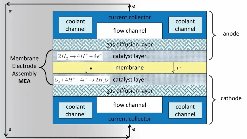
Figure 8- ANSYS Fluent: PEM Fuel Cell (PEMFC) Model Schematic
If you want to learn this software properly, we offer a prepared CFD simulation training . This practical simulation tutorial shows the workflow needed to set up a PEM fuel cell simulation accurately in ANSYS Fluent (Fig. 9). This hands-on tutorial walks you through geometry, meshing, model setup, and validation against a published research paper (Fig.10), ideal for students, researchers, and professionals in fuel cell R&D. Simulations like this not only enhance our understanding of how hydrogen fuel cells behave in practice but also help in optimizing hydrogen fuel cell efficiency and improving real-world design for commercial applications.

Figure 9- Proton Exchange Membrane Fuel Cell (PEMFC) CFD Simulation | Numerical Paper Validation
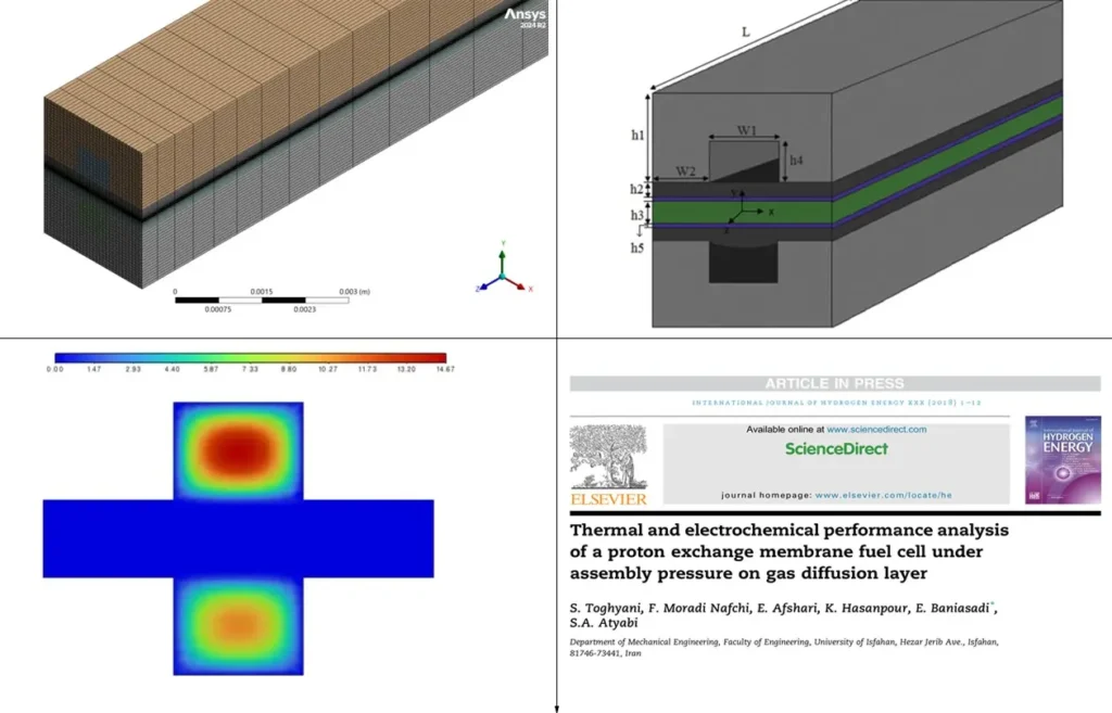
Figure 10- Thermal and electrochemical performance analysis of a proton exchange membrane fuel cell under assembly pressure on gas diffusion layer [5]
Performing an accurate electrochemical simulation helps engineers understand actual system behavior. It is the best method to optimize cell efficiency, manage heat generation, and improve real-world designs before manufacturing begins.
How to Enable the Fuel Cell Module in ANSYS Fluent
By default, the fuel cell module is not activated in ANSYS Fluent. Important Note: Fuel cell models are typically available only when you start the software in 3D double-precision mode. To use the model, you must load it as an add-on module. You can do this using the Text User Interface (TUI) or the Ribbon menu.
Follow these steps for the TUI method:
- Open ANSYS Fluent in 3D double-precision and proceed to the main setup window.
- In the command line area at the bottom of the window, type the following command:
/define/models/addon-module(Note that the activation process has changed in newer versions of ANSYS Fluent. If you are using an older version, you should type:/define/models/fuel-cell yes) - A list of available add-on modules will appear (Fig. 11). Find the number corresponding to the fuel cell model in the list.
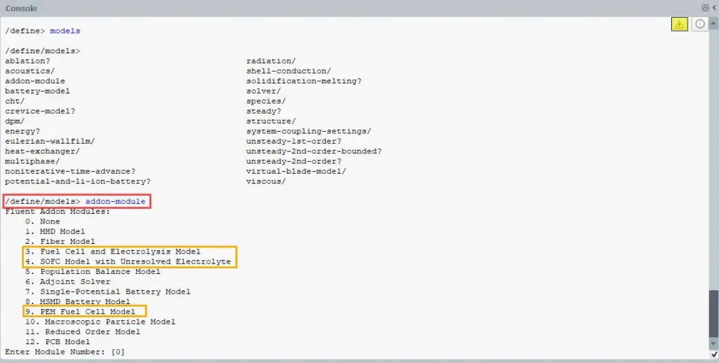
Figure 11- The process of activating the Fuel Cell Model in the command line area of ANSYS Fluent
- Type the number (e.g., enter
3for the Fuel Cell and Electrolysis Model, or9for the PEM Fuel Cell Model) and press Enter to activate it. - Once activated, the Fuel Cell dialog box will become available under the Models tree. Alternatively, you can use the graphical interface by going to the Physics tab, clicking More in the Models group, and selecting your module. You can now configure the settings (Fig. 12). During this step, you must identify and assign your physical zones, such as the current collectors, gas diffusion layers, catalyst layers, and the membrane.
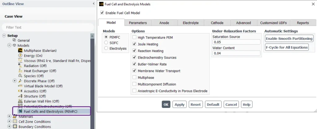
Figure 11- Schematic of the Fuel Cells and Electrolysis Models panel in ANSYS Fluent
Fuel Cells and Electrolysis Models interface in ANSYS Fluent
Figure 12 shows the setup interface for a fuel cell CFD simulation in ANSYS Fluent.
Model Tab:
- Models: Three main options are available:
- PEMFC (Proton Exchange Membrane Fuel Cells)
- SOFC (Solid Oxide Fuel Cells)
- Electrolysis
- Options: Features like High Temperature PEM, Joule Heating, Reaction Heating, Electrochemistry Sources, and Membrane Water Transport can be turned on or off based on your simulation needs.
- Under-Relaxation Factors: Parameters for Saturation Source (default: 0.05) and Water Content (default: 0.04) are adjustable. These help keep the numerical calculation stable during iterations.
- Automatic Settings:
- Enable Smooth Partitioning: Helps optimize the mesh handling and calculation speed.
- F-Cycle for All Equations: Ensures safe convergence while the solver runs.
Other Tabs at the Top: The interface allows switching between tabs for further configurations:
- Model: (Current tab).
- Parameters: Used for global and specific simulation settings.
- Anode, Electrolyte, Cathode: Used to define exact materials and boundary conditions for each physical part.
- Advanced: Provides additional solver or model refinements.
- Customized UDFs: Used to load User-Defined Functions for custom physical behaviors.
- Reports: Used for post-processing and checking analysis outputs.
The PEM Fuel Cell Model setup in ANSYS Fluent
As you already know, a Proton Exchange Membrane Fuel Cell (PEMFC) converts chemical energy directly into electrical energy through electrochemical reactions. The PEM fuel cell model in ANSYS Fluent provides a complete framework. It allows engineers to simulate and analyze the physical, chemical, and thermal processes inside the fuel cell. To set up an accurate fuel cell CFD simulation, you should follow these structured steps.
1. Configure the Model Tab: In the Model tab shown here (Fig. 13), you first enable the PEMFC simulation. You can customize key options such as Joule Heating, Reaction Heat, and Electrochemistry Sources for thermal modeling. You should also select the Butler-Volmer Rate and Multi-Component Diffusion for accurate species transport analysis.
2. Define Cell Zones and Materials You must assign the correct zone conditions to your geometry mesh (such as the Anode Gas Channel, Membrane, and Cathode Catalyst Layer). Next, define the properties for the gas mixtures (e.g., H2/H2O at the anode and O2/N2/H2O at the cathode). You will also specify parameters like Membrane Conductivity and Exchange Current Density. Important properties for the Gas Diffusion Layer (GDL), such as Anisotropic Proton Conductivity and Liquid Phase Dynamics, are configured here to manage water transport properly.
3. Set Boundary Conditions In the boundary settings, you specify the mass flow rate, species mass fractions (including relative humidity), and temperature at the inlets. At the current collector boundaries, you must define the electrical conditions, such as the total Voltage or Current Density.
4. Solution Controls and Initialization For a stable electrochemical simulation, it is recommended to use the Coupled solver. Perform a Hybrid Initialization before you begin the calculation.
Additional tabs in the interface allow configuring electrode designs (Anode/Cathode), electrical system setups (Electrical Tabs), advanced customization (Advanced), and scripting with UDFs. Each tab helps tailor the simulation to your exact engineering requirements.
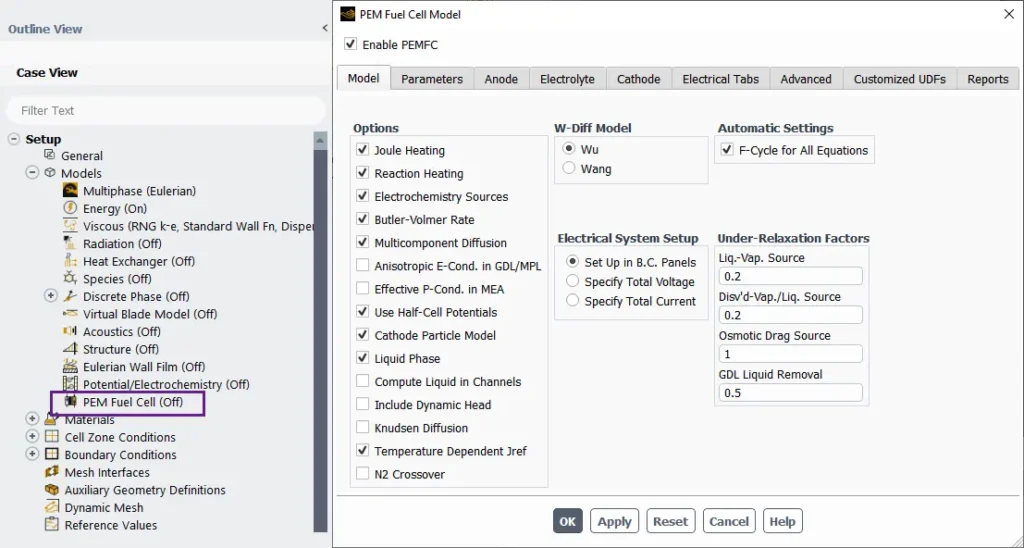
Figure 13- Schematic of the PEM Fuel Cell Model panel in ANSYS Fluent
The SOFC (Solid Oxide Fuel Cell) Model setup in ANSYS Fluent
Similarly, the SOFC model in ANSYS Fluent provides a complete framework for simulating solid oxide fuel cells. Users typically choose the unresolved electrolyte model for system-level studies (Fig. 14), though a resolved model is available for micro-scale analysis.
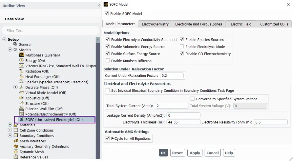
Figure 14- Schematic of the SOFC Model panel in ANSYS Fluent
This model is ideal for studying electrochemical reactions, heat transfer, and fluid flow in high-temperature systems. When performing a solid oxide fuel cell simulation, you must configure the following key features in the Model Options tab:
- Enable Volumetric Energy Source: Includes heat generation in the electrolyte and electrode regions.
- Enable Surface Energy Source: Activates reaction energy sources at the catalytic surfaces (often called the Triple Phase Boundary).
- Solution Under-Relaxation Factor: Specifies the relaxation factor for the current solution. SOFC models are often numerically sensitive. Reducing under-relaxation factors for species (0.7–0.8), energy (0.8), and potentials (0.5–0.7) ensures numerical stability during convergence.
- F-Cycle for All Equations: Optimizes the algebraic multigrid (AMG) solver to improve calculation speed for all equations.
Additional Tabs:
- Electrochemistry: Used to configure reaction kinetics (like the Butler-Volmer model) and define the exchange current density for the electrodes.
- Electrolyte and Porous Zones: Sets up the electrical and ionic conductivity of the electrolyte (such as YSZ) and the porous media for the fuel cell.
- Electric Field: Defines the electric field properties and system coupling.
- Customized UDFs: Allows engineers to add User-Defined Functions for advanced CFD simulation customization
Conclusion
As the world shifts toward sustainable energy, fuel cells stand out as a clean, efficient, and scalable solution. Technologies like hydrogen systems and PEM fuel cells offer promising alternatives to traditional combustion engines and power plants. Their zero-emission performance, especially in vehicles and portable power, makes them essential for future energy systems. With the support of fuel cell modeling and CFD simulations in ANSYS Fluent, researchers and engineers can easily optimize their designs, improve system efficiency, and reduce physical testing time. As infrastructure improves, fuel cells will play a leading role in the global clean energy transition.
Reference
[1] Armenta-Déu, C. (2025). A Fuel Cell Control System for Performance Improvement under Variable Atmospheric Pressure Conditions. Recent Progress in Science and Engineering, 1(1), 1-20.
[2] Ramadhani, F., Hussain, M. A., & Mokhlis, H. (2019). A comprehensive review and technical guideline for optimal design and operations of fuel cell-based cogeneration systems. Processes, 7(12), 950.
[3] Sebbani, I., Ettouhami, M. K., & Boulakhbar, M. (2025). Fuel Cells: A Technical, Environmental, and Economic Outlook. Cleaner Energy Systems, 100168.
[4] Samsudin, A. M., Bodner, M., & Hacker, V. (2022). A brief review of poly (vinyl alcohol)-based anion exchange membranes for alkaline fuel cells. Polymers, 14(17), 3565.
[5] Toghyani, S., Nafchi, F. M., Afshari, E., Hasanpour, K., Baniasadi, E., & Atyabi, S. A. (2018). Thermal and electrochemical performance analysis of a proton exchange membrane fuel cell under assembly pressure on gas diffusion layer. International Journal of Hydrogen Energy, 43(9), 4534-4545.