

Have you ever wondered what a heat sink does? Simply put, a heat sink is a device that helps keep electronic parts cool. Many devices, like your computer’s CPU or a powerful LED light, generate significant heat when they work. If they get too hot, they can break or stop working well. This is where proper thermal management becomes very important. This is a fundamental concept in Heat Transfer, where we control the movement of thermal energy to ensure reliability.
So, what is a heat sink? It is usually a piece of metal, often aluminum or copper, with many fins. What does a heat sink look like? Imagine a metal block with thin, tall walls (fins) sticking out of it. The main job of a heat sink is heat dissipation—to take heat away from a hot part and release it into the surrounding air or liquid.
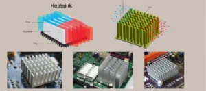
Figure 1: Examples of common heat sinks (passive and active) used for thermal management to prevent electronic components from overheating.
How does a heat sink work? It uses two main ways to move heat:
- Conduction: Heat first moves from the hot electronic part into the metal base of the heat sink. Then, it spreads through the metal fins. Metals like copper and aluminum are good at conduction.
- Convection: As the fins get hot, they heat the air (or liquid) around them. This warmer air rises and cooler air takes its place, carrying the heat away. The fins help by giving a large surface area for the air to touch, making this process faster.
Heat sinks are essential for preventing electronic parts from overheating, ensuring they work correctly and last longer. Sometimes, a passive heat sink (just the metal) is not enough. For very hot parts, an extra heat sink fan is often used. This fan blows air over the fins, speeding up the convection process and removing heat much faster. This combination is common in computers and other high-performance electronics. Understanding these basics is the first step to designing effective cooling solutions.
Common Types and Applications of Heat Sinks
Heat sinks come in many shapes and sizes, each designed for different cooling needs. The geometry, especially the fin arrangement, greatly changes the heat dissipation efficiency. Understanding these types helps in choosing the right one for specific electronic cooling applications.
Here are some common types used in the industry:
- Plate Fin Heat Sinks: This is the most common answer to “what does a heat sink look like?”. It features flat, parallel fins standing up from a base. They are easy to manufacture and work exceptionally well when airflow is unidirectional (straight line). You will often find these in desktop computers and power supplies where a heat sink fan blows air directly through the channels.
- Pin Fin Heat Sinks: Instead of flat plates, these have an array of small, round or square pins. This design allows air to flow in any direction, making them ideal for unpredictable airflow environments. However, they typically create more pressure drop, which must be checked during Heat sink CFD analysis.
- Skived Fin Heat Sinks: These are made by slicing and lifting thin layers of metal from a single block. This method creates extremely thin fins with high density, offering more surface area in a compact space. They are excellent for heat sink design optimization in high-power devices where space is tight.
- Bonded Fin Heat Sinks: For very tall fins that cannot be extruded, individual fins are bonded (glued or soldered) onto a base. This allows for a much higher aspect ratio, making them suitable for cooling very powerful industrial components.
- Folded Fin Heat Sinks: These use thin sheets of metal folded into a wavy or accordion shape. They offer a good balance of performance and cost and are often used in automotive electronics.
- Microchannel Heat Sinks: These are advanced devices with tiny channels (smaller than 1mm) designed for liquid flow. They are extremely effective at removing heat from high-performance microchips. You can learn more about simulating these in our Microchannel Heat Sink CFD Simulation tutorial.
The choice depends on factors like heat load, available space, and manufacturing cost. Each type has its own advantages, and engineers often use Heat sink ANSYS simulation to compare different designs and get the best thermal performance evaluation for their specific project.
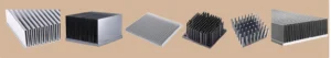
Figure 2: Various heat sink types, including plate fin, pin fin, and skived fin designs, each suited for different cooling needs and flow conditions.
The Science Behind Cooling: How Heat Sinks Transfer Heat
To truly understand how does a heat sink work, we need to look at the basic science of heat transfer. Heat always moves from a hot place to a colder place. Heat sinks use three main ways to move this heat: conduction, convection, and radiation. While all three are present, conduction and convection are the most important for heat sinks.
- Conduction:
Conduction is how heat travels through solid materials. When a hot electronic component touches the base of the heat sink, heat flows directly from the component into the metal. From the base, it spreads throughout the fins. This is why material selection is critical; materials with high thermal conductivity, like copper and aluminum, are chosen because they transfer heat very efficiently. - Convection:
Convection is how heat moves from the solid fins into the surrounding fluid (air or liquid). As the fins become hot, they heat the fluid touching them. This warmer fluid becomes lighter and rises (or is pushed away), allowing cooler fluid to take its place. This continuous cycle carries heat away. The more surface area the fins have, the more contact they have with the fluid, significantly increasing heat dissipation. - Radiation (Minor Role):
Radiation plays a minor role in most active cooling setups but contributes to passive cooling. It involves heat moving through electromagnetic waves, similar to how the sun warms the Earth.
To improve performance, engineers often use forced convection. This involves adding a heat sink fan to force air over the fins at a higher velocity. Faster air movement means more cool air constantly touches the hot fins, which greatly speeds up the heat transfer process.
The overall ability of a heat sinks to remove heat is quantified by its thermal resistance ( ). A lower thermal resistance means the heat sink is better at keeping the component cool. This metric is the “gold standard” in Heat sink thermal analysis and allows engineers to compare different designs objectively.
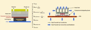
Figure 3: Heat transfer modes in a heat sink — Conduction spreads heat through the metal fins, while Convection releases it into the surrounding fluid.
Simulating Heat Sinks: Key Parameters for Design
Designing a good heat sink is not just about guessing. Engineers use powerful computer programs, like ANSYS Fluent, for Heat sink CFD analysis. This allows them to see how a device will perform before it is even built. Simulation helps us understand the heat sink design parameters and predict heat sink performance analysis accurately.
Here are the most important parameters we analyze in a Heat sink ANSYS simulation:
- Temperature Distribution (Temperature Contour):
This shows how hot or cold different parts of the heat sink and the electronic component become. A temperature contour is a map of temperatures across the surface.
It is crucial for finding hot spots and ensuring the electronic part stays below its maximum safe temperature. For example, a simulation might show that the center of the CPU is 90°C, while the heat sink fins are only 60°C. This helps engineers see if the heat sink is working well enough. - Thermal Resistance (Rth):
This is a very important number for thermal performance evaluation. Thermal resistance tells us how well a heat sink moves heat away. A lower Rth means the heat sink is better at cooling. It is measured in °C/W (degrees Celsius per Watt). For example: If a CPU produces 50 Watts of heat and the heat sink has Rth = 0.5 °C/W, the temperature rise across the heat sink will be 25°C. - Pressure Drop (ΔP):
When air flows through a heat sink, it faces resistance. This causes a pressure drop. A high pressure drop means the fan must work harder, requiring more power and creating more noise. Engineers must balance low thermal resistance with an acceptable pressure drop for efficient system operation.
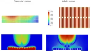
Figure 4: Temperature contour (left) and velocity streamlines (right) from heat sink Fluent simulation — essential outputs for thermal performance evaluation.
- Heat Transfer Coefficient and Nusselt Number:
These numbers tell us how well heat moves from the surface of the fins into the air or liquid. A higher heat transfer coefficient means more heat is being moved away from the fins. The Nusselt number (Nu) is a way to compare heat transfer in different situations. - Velocity Distribution (Velocity Contour) and Streamline Visualization:
A velocity contour shows how fast the air is moving in different areas. Streamline visualization tracks the path of the airflow. These are vital for understanding flow patterns, finding areas where air might get stuck (recirculation), and performing heat sink design optimization. - Heat Flux Contour:
This shows the rate of heat flow per unit area. It helps identify exactly where heat is entering or leaving the surface most intensely. By carefully studying these outputs, engineers can achieve better heat sink efficiency. For example, our tutorial on ANSYS Heat Sink Simulation shows how these parameters are extracted and analyzed to evaluate a standard finned heat sink.
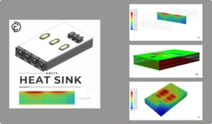
Figure 5: CFDLand heat sink CFD simulation tutorials in ANSYS Fluent help engineers study thermal resistance, temperature distribution, and pressure drop before building real prototypes.
Optimization and Advanced Considerations in Heat Sink Design
After understanding the different parameters from simulation (Section 3), engineers don’t just stop there. They use these insights to make the heat sink even better. This process is called heat sink design optimization. The goal is to get the best cooling performance while considering other important factors like cost, size, and the power needed for fans or pumps. This optimization involves finding the perfect balance of geometry. Engineers run simulations where they change heat sink design parameters such as fin height, thickness, spacing, and base thickness. By testing these variables, they can find a combination that gives the lowest thermal resistance () without causing a massive pressure drop that would require a noisy, high-power fan.
Here’s how engineers push the boundaries of heat sink design:
- Heat Sink Design Optimization:
This means finding the best possible design. Engineers change different heat sink design parameters, such as:- Fin Height and Thickness: How tall and thick the fins are.
- Fin Spacing: The distance between the fins.
- Number of Fins: How many fins are on the heat sink.
- Base Thickness: The thickness of the heat sink’s base. By running many simulations with different values for these parameters, they can find the combination that gives the lowest thermal resistance with an acceptable pressure drop. This leads to better heat sink efficiency.
- Heat Sink Material Selection:
Another critical decision is heat sink material selection. The material choice greatly affects thermal performance evaluation. Copper is often favored for high-performance applications because of its very high thermal conductivity, though it is heavy and expensive. Aluminum is lighter and cheaper but has lower conductivity. Engineers use Heat sink ANSYS simulation to determine if the extra cost of copper is truly needed or if aluminum is sufficient for the specific heat load. - Heat Sink Sizing:
Simulation also guides heat sink sizing—finding the right length, width, and height. If a heat sink is too small, it will overheat; if it is too big, it wastes space and money. - Advanced Cooling Techniques:
For very hot electronic components or when space is extremely limited, standard air-cooled heat sinks might not be enough. This is where advanced methods come in, and CFD (Computational Fluid Dynamics) simulation becomes even more important:- Liquid Cooling: Instead of air, a liquid (like water or a special coolant) flows through channels in a cold plate attached to the hot part. Liquid can absorb much more heat than air, making it very effective.
- Microchannel Heat Sinks: These are a type of liquid cooling where the channels are extremely small (like tiny tubes). They offer very high heat transfer in a compact area.
- Phase Change Materials (PCMs): These materials absorb a lot of heat when they change from solid to liquid (like ice melting). They can provide temporary cooling for sudden bursts of heat.
- Porous Media: Using materials with many tiny holes can increase the surface area for heat transfer in a compact volume, often used with forced convection.
Through careful heat sink design optimization and considering advanced techniques, engineers can create highly effective cooling solutions for even the most demanding applications.
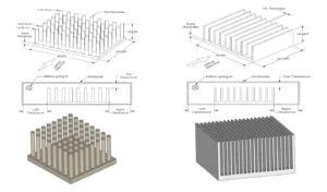
Figure 6: Key geometry parameters for optimization—fin height, thickness, spacing, and number of fins—used as inputs in ANSYS Fluent.
The Simulation Process: Performing Heat Sink CFD Analysis
Now that we understand what is a heat sink and its key performance parameters, let’s look at how does a heat sink work in a virtual environment. Heat sink simulation is a powerful tool for engineers to test designs without building physical models. This process, often called heat sink CFD analysis, involves several important steps, typically using software like ANSYS Fluent.
Here are the main steps in a typical electronic cooling simulation:
- Geometry Creation:
First, the heat sink, the electronic component, and the surrounding space (where air or liquid will flow) are drawn in a 3D modeling tool. This digital model is the “geometry.” It needs to be very precise to match the real object. - Meshing:
Next, this 3D geometry is divided into many small, simple shapes called “cells” or “elements.” This process is called meshing. Imagine breaking a complex shape into tiny bricks. The computer solves equations for each of these small cells. A good mesh is crucial for accurate heat sink thermal simulation results. Areas with complex flow or high temperature changes need smaller cells. - Setup in ANSYS Fluent (or similar software):
This is where we tell the software all the conditions of our problem:- Material Properties: We define what the heat sink is made of (e.g., aluminum, copper) and what fluid is flowing (e.g., air, water).
- Heat Source: We tell the software how much heat the electronic component is producing (e.g., 50 Watts).
- Boundary Conditions: These are the rules for the edges of our simulation area. For example:
- Inlet: How fast the air is entering and its temperature.
- Outlet: The pressure at which air leaves.
- Walls: We define if surfaces are slippery (no-slip) or if they conduct heat.
- Models: We choose mathematical models for things like turbulence (how air swirls) if the flow is fast.
4. Solving:
Once everything is set up, the computer starts to calculate. It uses complex equations to find the fluid velocity, pressure, and temperature in every single cell of the mesh. This step can take from minutes to hours, depending on the complexity of the design and the power of the computer.
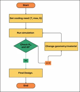
Figure 7: The iterative process of heat sink design using simulation outputs.
5. Post-Processing and Analysis:
After the calculation is finished, we look at the results. This is where we get our insights:
-
- Temperature Contour: We can see a map of temperatures across the heat sink and component, identifying hot spots.
- Velocity Contour and Streamline Visualization: We can see how fast the fluid is moving and its path, helping to understand airflow and heat sink efficiency.
- Heat Flux Contour: This shows where heat is being transferred most intensely.
- We can also calculate the thermal resistance and pressure drop from these results, which are key for heat sink thermal performance evaluation.
This step-by-step heat sink CFD analysis allows engineers to quickly test and refine designs, leading to better and more efficient cooling solutions. For a practical example of how these steps are implemented, you can explore tutorials like ANSYS Heat Sink simulations available on CFDLand.com, which walks through a typical heat sink design optimization process.
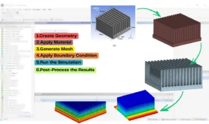
Figure 8: Setting up the geometry, mesh, Boundary Condition and Post-Process for a heat sink in ANSYS Fluent, a crucial step in heat sink CFD analysis.
Advanced Heat Sink Simulations: Examples and Key Outputs
In some cases, we use advanced models to get better cooling or study special designs. These models use features like microchannels, porous media, nanofluids, or spray cooling. Each one brings new parameters to check in simulation. We give clear examples using real CFDLand tutorials to show how these outputs look.
Microchannel Heat Sinks
A microchannel heat sink uses many small channels for the fluid. This gives a much larger surface area and can cool parts better. The main outputs are thermal resistance, Nusselt number, pressure drop, and temperature contour. Key Outputs are Nusselt number (Nu) for each channel, temperature and velocity contours, pressure drop value.
Porous Media Heat Sinks
A porous media heat sink has a region where the fluid flows through tiny paths. The important outputs here are porosity, pressure drop, and thermal resistance. For instance, in Porous Microchannel Heat Sinks CFD Simulation, simulation measures porosity effect on cooling and flow. We Compare temperature contour and pressure drop for different porosity values.
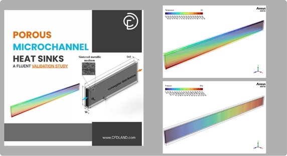
Figure 9: Analyzing the effect of porosity in a porous media heat sink using CFD simulation, comparing temperature contours to optimize heat dissipation.
Nanofluids in Heat Sinks
A nanofluid is a fluid with small particles (nanoparticles) inside. This can raise the heat transfer coefficient and lower the thermal resistance. The outputs you check are nanoparticle volume fraction, temperature contour, pressure drop, and Nusselt number. For better understanding, check Two-Phase Nanofluid in Minichannel Heat Sink which shows the effect of adding nanoparticles and using two-phase or mixture models.
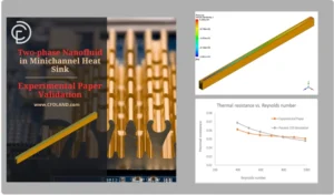
Figure 10: Investigating the enhanced cooling of a heat sink using nanofluids in a two-phase flow simulation to calculate the improvement in the heat transfer coefficient
Spray Cooling and DPM Wall Film
Spray cooling uses small droplets to cool the surface. In simulation, you use the DPM (Discrete Phase Model) and track wall film thickness and evaporation rate. Outputs include temperature contour, film thickness plot, and cooling efficiency. A case in point is DPM Wall Film on Heat Sink Due to Spray Cooling that explains how spray cooling can quickly drop surface temperature. It studies Wall film thickness, evaporation rate, temperature drop across the surface.
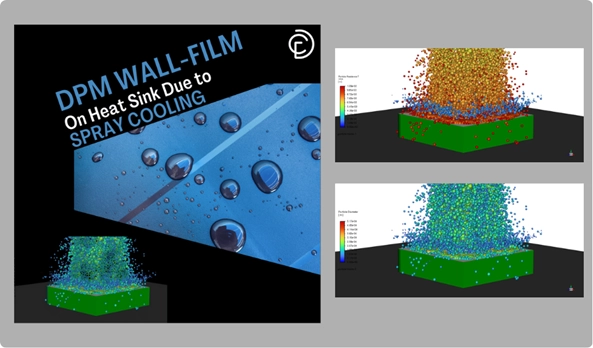
Figure 11: A DPM wall film simulation visualizing spray cooling on a heat sink, where key outputs include evaporation rate and surface temperature drop for rapid thermal management.
Natural Convection from Fins
Sometimes we need to cool with no fan—just air moving from heat. This is natural convection or passive cooling. Outputs are Rayleigh number, Nusselt number, and temperature contour. Natural Convection from Heat Sink Fins shows how fins cool the surface using only air movement.
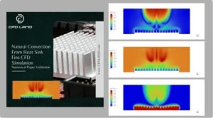
Figure 12: Simulation of passive cooling showing natural convection from heat sink fins, with velocity contours illustrating the buoyancy-driven airflow and analysis of the Rayleigh number.
Conclusion: The Critical Role of Heat Sinks in Modern Technology
Throughout this article, we answered the fundamental questions: what is a heat sink and how does it work? We have seen that these devices are essential for the thermal management of almost all modern electronics. From a small LED to a powerful computer server, heat sinks ensure that components stay cool, operate reliably, and last longer through effective heat dissipation.
The core of modern engineering lies in heat sink CFD analysis. By using simulation software like ANSYS Fluent, engineers can perform a detailed heat sink thermal performance evaluation before building a physical prototype. This involves examining crucial heat sink design parameters like temperature distribution, thermal resistance (), and pressure drop (ΔP). This data-driven approach allows for precise heat sink design optimization, preventing overheating and maximizing heat sink efficiency.
Figure 13: CFDLand offers a comprehensive library of heat sink simulation tutorials for mastering CFD analysis and designing effective electronic cooling solutions in ANSYS Fluent.
To learn more, explore CFDLand’s heat sink thermal simulation tutorials. CFDLand offers step-by-step guides for heat sink CFD analysis, electronic cooling simulation, and heat sink design optimization.