
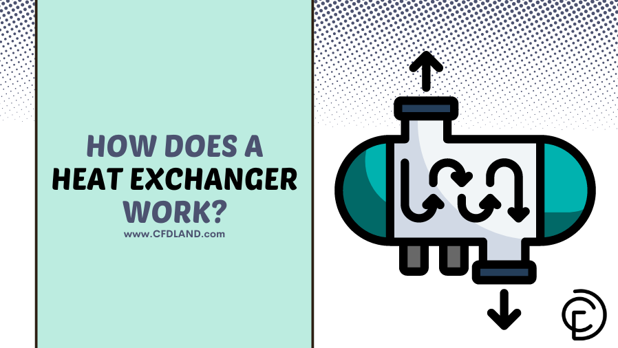
A heat exchanger is a mechanical device that transfers heat from a hot fluid to a cold fluid. These fluids can be either liquids or gases. Before setting up any heat exchangers CFD simulation, as a mechanical engineer we are bound to first understand how these devices operate in the real world.
So, how do they work? In most designs, the two fluids never mix or touch each other. Instead, they are hot and cold fluids separated by a solid wall. Heat naturally moves through this metal wall from the hot side to the cold side. This simple process allows systems to heat up or cool down safely and efficiently.

Figure 1: A basic heat exchanger transfers heat without allowing the hot and cold fluids to mix.
The Core Mechanism: How a Heat Exchanger Works
A heat exchanger works by allowing thermal energy to pass from a hotter fluid to a cooler fluid without the two fluids ever mixing. The fluids can be liquids, such as water or oil, or gases, such as air or steam. To understand the core mechanism, imagine a simple pipe with another larger pipe around it. The inner pipe carries a hot liquid, while a cooler liquid flows through the outer pipe at the same time. In this setup, we have hot and cold fluids separated by a solid wall.
Because heat naturally flows from a hotter area to a cooler area, the thermal energy leaves the hot fluid, travels directly through the metal wall of the inner pipe, and enters the cooler fluid. As the fluids travel along the length of the pipes, the hot fluid safely cools down, and the cold fluid safely warms up. For example, if hot oil enters at 80°C and cooling water enters at 30°C, the heat leaves the oil and enters the metal wall. The metal conducts this heat to the cold water on the other side. The metal wall ensures that there is no direct contact, keeping the two streams completely isolated from each other at all times. This basic physical action is the core mechanism of every heat exchanger, no matter how large or complex the system is.

Figure 2: A typical mechanism example showing an inner pipe carrying hot fluid and an outer pipe carrying cold fluid, separated by a solid boundary.
Working Principle & Thermodynamics
The working principle of a heat exchanger relies on simple thermodynamics: heat always moves naturally from a high temperature to a low temperature. This difference in temperature between the two fluids is called the thermal gradient.
The heat exchange process happens in three physical steps. First, the hot fluid transfers its thermal energy to the surface of the solid wall. This is called convection. Second, the heat travels straight through the thickness of the metal wall. This is called conduction. Third, the heat moves from the wall’s other surface into the cold fluid through convection again.

Figure 3: Heat moves into the wall by convection, travels through the metal by conduction, and enters the cold fluid by convection.
To measure how easily heat passes through the wall, we use a metric called the Overall Heat Transfer Coefficient, or the U-value. A higher U-value means the heat exchanger works more effectively. Engineers also use specific math formulas to calculate how much heat transfers from one end of the device to the other. For a detailed look at how to calculate these temperatures, you can read our complete guide on the Log Mean Temperature Difference (LMTD) method.

Figure 4: There are different math formulas to assess the performance of a heat exchanger
What’s Inside a Heat Exchanger
What is really inside a heat exchanger? To understand this, we can look at the most common design in the industry: the shell and tube heat exchanger. The main internal parts are the tubes, the tube sheet, the shell, and the baffles.
- The Tubes: These are small metal pipes. The first fluid (called the tube-side fluid) flows directly inside these tubes.
- The Shell: This is the large outer container that holds the tube bundle. The second fluid (called the shell-side fluid) flows through this main body, passing over the outside of the tubes.
- The Tube Sheet: This is a thick metal plate at the ends of the heat exchanger. The tubes are rolled and fitted tightly into this plate. The tube sheet creates a leak-tight seal so the high-pressure and low-pressure fluids never mix.
- The Baffles: These are internal support plates placed inside the shell. They hold the tubes in place and direct the shell-side fluid back and forth across the tubes. This back-and-forth movement increases the heat exchange process.
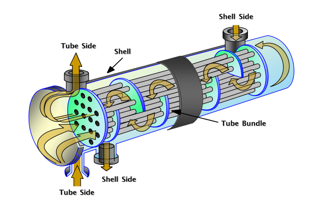
Figure 5: The internal parts of a shell and tube heat exchanger. Baffles direct the flow to improve heat transfer.
While the basic purpose of baffles is to induce turbulence and increase heat transfer efficiency, they serve a second, critical mechanical function in industrial applications. As fluids move at high velocities, they create vibrations. Baffles act as physical supports for the tubes, preventing flow-induced vibration damage and helping the bundle withstand severe thermal expansion and pressure drops.
The Heat Exchange Process (Passes)
How does the fluid travel from the inlet to the outlet? Designers define this step-by-step journey by the number of “passes” a fluid makes inside the system. A pass refers to the physical movement of a fluid from one end of the heat exchanger to the other.
- Single Pass: The fluid uses a straight pipe. It enters at one end of the heat exchanger and exits at the other end very quickly.
- Double Pass: The internal pipe bends into a U-shape. The fluid travels down the length of the system, turns around, and exits at the exact same end where it entered.
- Triple Pass: The pipe bends into an S-shape. This forces the fluid to travel the full length of the device three times before finally exiting.
Increasing the number of passes forces the hot and cold fluids to spend much more time together, which drastically increases the total amount of heat transferred. However, this creates a major mechanical trade-off. Forcing a heavy fluid to constantly turn and travel longer distances causes significant pressure drops and a severe loss of flow velocity. Designers must carefully calculate the number of passes to maximize thermal efficiency without exceeding the pumping system’s safe pressure limits.

Figure 6: Although the number of passes can increase total heat transfer, designers should consider the increase in pressure drop as another important designing factor
Flow Arrangements: Parallel vs. Counter vs. Cross-Flow
How do the fluids move relative to each other inside the shell and tubes? We categorize heat exchangers by three main flow arrangements: parallel flow, counter flow, and cross-flow.
- Parallel Flow: Both the hot and cold fluids enter the device at the same end. They travel side-by-side in the same direction and exit together at the opposite end.
- Counter Flow: The fluids enter at opposite ends of the heat exchanger. They travel past each other in completely opposite directions.
- Cross-Flow: The two fluids travel at right angles (perpendicular) to each other.
Why does the flow direction matter? In thermodynamics, . Because the fluids move in opposite directions, the system maintains a high average temperature difference between them along the entire length of the pipes. In a pure counter flow setup, the cold fluid can actually absorb so much thermal energy that it exits the device hotter than the hot fluid’s exit temperature, a physical impossibility in a standard parallel flow design.

Figure 7: The three primary flow arrangements. Counter flow is widely used because it transfers the maximum amount of heat.
Types of Heat Exchangers by Construction
Beyond how the fluid flows, engineers classify heat exchangers by their physical shape and construction. Based on the industrial need, there are four main structural designs:
- Double Pipe: This is the most straightforward design. It consists of one simple pipe placed inside a larger pipe. It is very cheap to build and easy to maintain, but it has a relatively low heat transfer efficiency.
- Shell and Tube: This is the most common design in heavy industry. A bundle of metal tubes is surrounded by a large, sealed cylindrical shell.
- Plate Heat Exchangers: Instead of tubes, this design uses a tight stack of thin, corrugated metal plates. Fluids flow in the tiny spaces between the plates. This creates a massive surface area for heat to transfer very rapidly.
- Air Cooled: Found in cars (radiators) and outdoor industrial plants. Instead of using a cold liquid, these systems use fans to blow ambient air across a series of tubes to cool the hot fluid inside.
When choosing a design, we look at a metric called the compactness factor (measured in square meters of surface area per cubic meter of volume). Plate heat exchangers are incredibly compact and highly efficient. However, because the plates must be sealed together using large rubber or synthetic gaskets, they are prone to leaking under extreme conditions. Therefore, in high-pressure or high-temperature environments like power plants, engineers must sacrifice compactness and rely on the heavy, welded metal bodies of shell and tube heat exchangers to guarantee a safe, leak-tight seal.
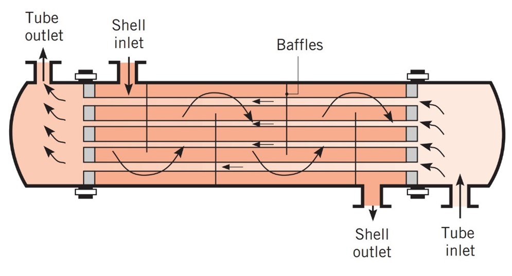
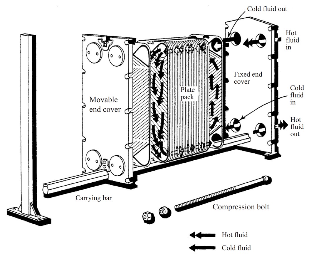


Figure 8: Heat exchangers are built in different shapes. Image from Incropera et al., Fundamentals of Heat and Mass Transfer, 7th edition, Wiley.
Heat Exchanger Materials
Our next question to be answered is, What are heat exchangers made of? To transfer heat safely, the walls of the device must be made of the correct material. The choice depends entirely on how hot the fluids are and whether they are corrosive (like acid or salt water).
- Metals: This is the most common choice. Metals like stainless steel, copper, and aluminum are excellent at absorbing and moving heat quickly.
- Plastics (Polymers): These are very light, cheap, and never rust. However, they cannot handle high heat. They are perfectly suited for low-temperature daily uses, like heating a swimming pool or a shower.
- Ceramics: These are used for extreme, heavy-duty situations. They do not melt easily and can resist harsh chemicals that would destroy normal metal.
- Composites: These blend materials together, giving engineers the light weight of plastic but the heat resistance of metal.
Choosing the wrong material leads to rapid failure. While standard metals offer great thermal conductivity, they have strict limits. For instance, in industrial applications exceeding 1000°C, common metals like copper and steel will melt, forcing engineers to use high-temperature ceramics. Furthermore, in marine applications where highly corrosive seawater is the cooling fluid, standard steel will quickly rust and erode. In these cases, designer must upgrade to highly resistant metals like titanium or cupro-nickel to protect the tube sheets from corrosion and flow-induced erosion.
Applications of Heat Exchangers
Honestly speaking, Heat exchangers are absolutely everywhere in our daily lives and in heavy industry. Their main job is to save energy, control temperatures, and prevent machines from overheating.
- Power Generation: Huge power plants use massive condensers to cool down hot steam and turn it back into liquid water so it can be reused in the boiler.
- Vehicles: Your car uses a radiator. This is an air-cooled heat exchanger that uses the wind from driving to cool the hot engine fluid.
- HVAC Systems: Air conditioners and refrigerators use special heat exchangers called evaporators and condensers to absorb heat from your room and push it outside.
- Waste Heat Recovery: Factories use recuperators and regenerators to capture hot exhaust gases leaving a chimney. They use this free, wasted heat to warm up fresh air coming into the building, which saves massive amounts of fuel and money.

Figure 9: Heat exchangers are essential in everyday life, from cooling car engines to generating global electricity. The variety of applications are greatly discussed by Pooja Nandakumar et al.
Each application has strict physical limits. For example, in a power plant steam condenser, engineers must maintain a nearly perfect internal vacuum (around 29 inches of Mercury) to maximize the expansion of the steam and the electrical output of the turbine. In marine applications, using raw seawater as a coolant introduces severe erosion and corrosion risks. Standard steel would quickly rust, so marine heat exchangers must be built using highly expensive materials like titanium or 90/10 cupro-nickel, and they often require sacrificial anodes to protect the tube sheets from chemical decay.
Compactness & Efficiency
In order to evaluate the performance of a heat exchanger whether it is good in job or not, we look at two major factors: how small it is (compactness) and how much thermal energy it successfully moves (efficiency).
- Compactness: This is measured by how much heat transfer surface area exists inside one cubic meter of volume. If a device has more than 700 square meters of surface area per cubic meter, it is officially classified as a compact heat exchanger.
- Flow Rate: Pumping more fluid through the system increases the total heat transfer. However, pushing heavy fluids faster requires massive pumps and causes severe pressure drops.
- Temperature Cross-Over: This happens when the cold fluid actually gets hotter than the hot fluid’s exit temperature. This can seriously reduce the efficiency of the device if not controlled properly.
To measure efficiency and design the perfect size for a system, we cannot rely on simple average temperatures. Because the temperature of both fluids changes continuously as they travel down the length of the pipes, they must calculate the thermal performance using advanced thermodynamics. To do this, engineers conduct the LMTD vs ε-NTU method for heat exchanger analysis. Simply put, the LMTD (Log Mean Temperature Difference) method is used when all inlet and outlet temperatures are known, while the NTU (Number of Transfer Units) method is required to predict performance when the exit temperatures are unknown.
Conclusion
Heat exchangers are very important tools in modern industry and daily life. They transfer thermal energy between fluids while keeping them completely separated. From simple double-pipe systems to highly advanced plate designs, the choice of construction depends on temperature, pressure, and fluid types. By selecting the correct materials and flow arrangements, we can maximize heat transfer while keeping pressure drops within safe limits.