


An annular jet pump is a very smart device that moves fluids without any moving parts. It uses a fast-moving stream of water (the primary flow) to pull along a slower stream (the secondary flow). The primary flow comes in as a ring shape around the outside, which works much better than older designs. This high-speed jet creates a powerful suction that can pull liquids from tanks or wells. Because they have no spinning parts to break, these pumps are very strong and last a long time, especially in dirty water. This Annular Jet Pump CFD study uses computer simulation to look inside and see how it works, based on a reference paper [1] that reported a pump efficiency of 11.5%. Understanding the flow helps us find ways to make these pumps even better.
- Reference [1]: Xu, Kai, et al. “Parameter analysis and optimization of annular jet pump based on kriging model.” Applied Sciences21 (2020): 7860.
- Reference [2]: Xu, Kai, et al. “Multi-objective optimization of jet pump based on RBF neural network model.” Journal of Marine Science and Engineering2 (2021): 236.
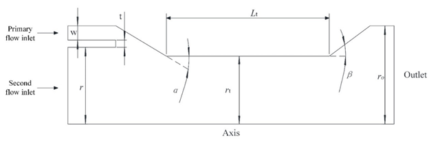
Figure 1: Schematic drawing of an Annular Jet Pump [1].
Simulation Process: Fluent Setup, Modeling the 2D Axisymmetric Jet Pump
To save computer time, we built a 2D axisymmetric model of the Annular Jet CFD pump, since it is perfectly round. This shape was then filled with a very neat, structured grid made of 390,307 quadrilateral cells to get accurate results. We used the realizable k-epsilon turbulence model to correctly predict how the fast and slow water streams would mix together. These settings were all based on the reference paper [1] to ensure our simulation was valid and correct.
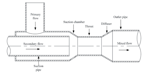
Figure 2: The 2D axisymmetric domain used for the Annular Jet Pump CFD simulation [1].
Post-processing: CFD Analysis, Visualizing Flow Dynamics and Turbulent Mixing
The effect of turbulent mixing is influenced by the jet pump structure parameters determining the jet pump performance. Dimensionless parameters, efficiency η and pressure ratio h, are introduced to study the jet pump performance. Their equations are (reference paper):
![\[ h = \frac{\Delta p_o}{\Delta p_p} = \frac{\left(p_o + \gamma_o \frac{V^2_o}{2g}+\gamma_o z_o \right) - \left( p_s + \gamma_s \frac{V^2_s}{2g}+\gamma_s z_s\right)}{\left( p_p + \gamma_p \frac{V^2_p}{2g}+\gamma_p z_p\right) - \left(p_o + \gamma_o \frac{V^2_o}{2g}+\gamma_o z_o \right)} \]](https://cfdland.com/wp-content/ql-cache/quicklatex.com-396e420883bc7a2e056b9a6cff24a1a5_l3.png "Rendered by QuickLaTeX.com")
![\[ \eta = \frac{Q_s}{Q_p}.\frac{\Delta p_o}{\Delta p_p-\Delta p_o}=q\frac{h}{1-h} \]](https://cfdland.com/wp-content/ql-cache/quicklatex.com-86ed20b7f40f99315d85c505d3e0123a_l3.png "Rendered by QuickLaTeX.com")
![\[ q= \frac{Q_s}{Q_p} \]](https://cfdland.com/wp-content/ql-cache/quicklatex.com-7ac08277e8f283361c92239e17f16b2a_l3.png "Rendered by QuickLaTeX.com")
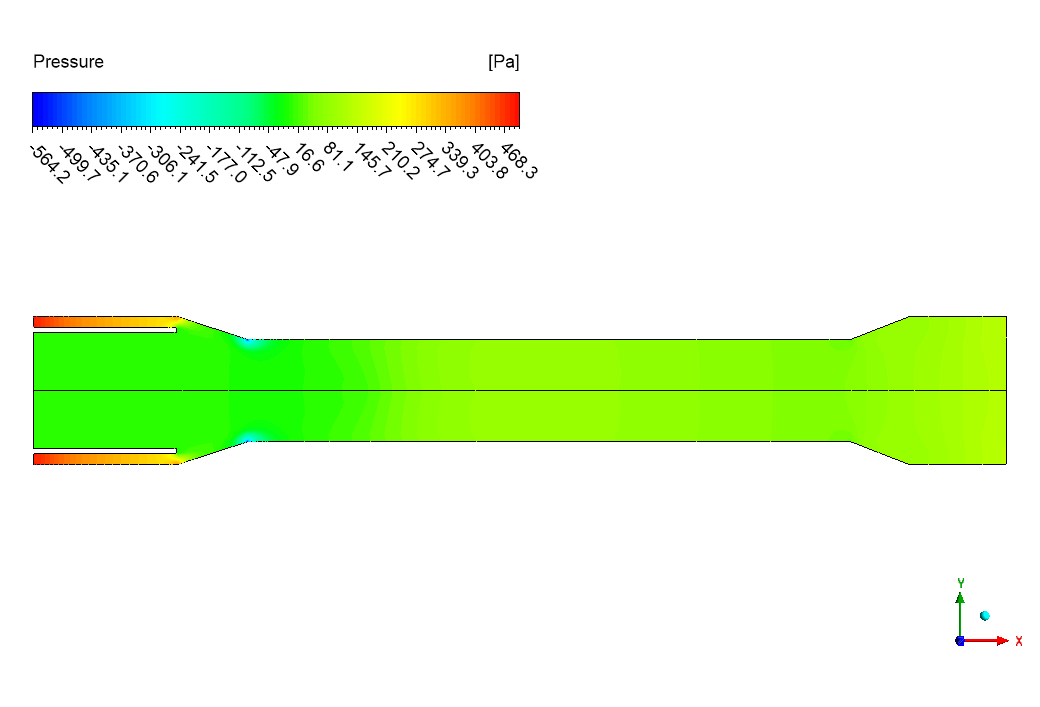
Given the reported efficiency of 0.115 (11.5%), this suggests that there’s significant room for optimization while the pump is operational. The relatively low efficiency might be due to energy losses during mixing, wall friction, or suboptimal geometry design. Further analysis and potential design modifications could be explored to improve the pump’s performance.
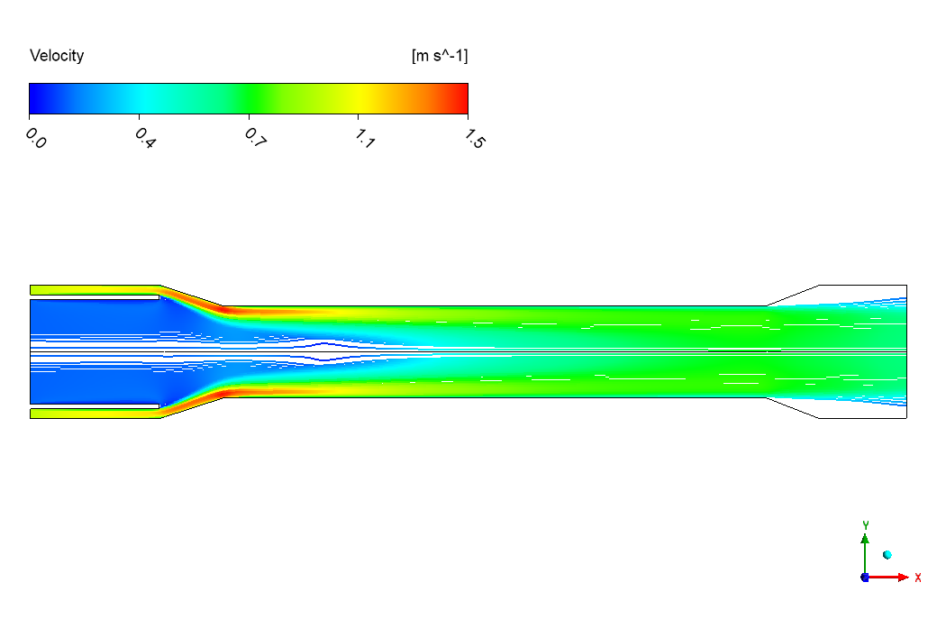
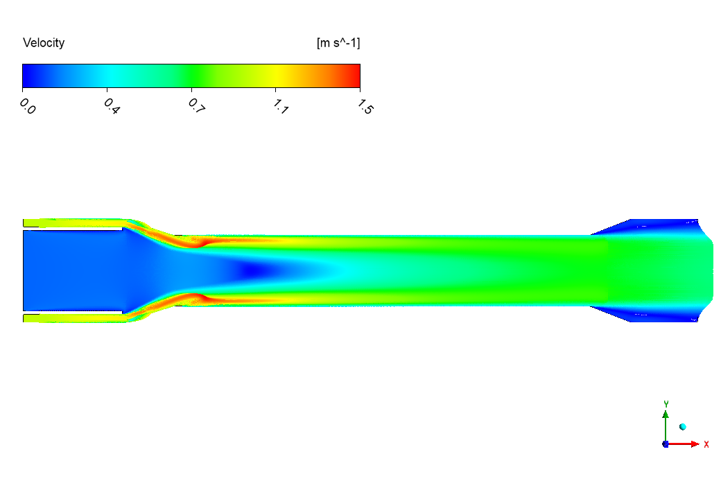
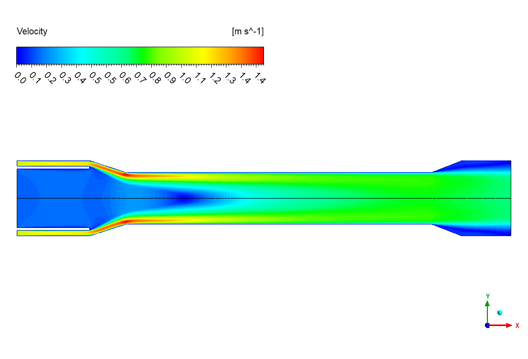
The velocity contour provides a clear visual of how the annular jet pump works. The primary flow enters and squeezes through the ring-shaped nozzle, speeding up to a maximum of 1.4 m/s. This high-speed jet creates a low-pressure area that sucks in the secondary flow. In the mixing chamber, the fast jet spreads out from the walls toward the center, sharing its energy and pulling the slower fluid along with it. As the combined flow enters the wider diffuser section on the right, it slows down to about 0.3-0.5 m/s. This slowing down is very important because it converts speed energy back into pressure energy, which is what creates the pumping effect.

Figure 3: Velocity distribution from the Annular Jet Fluent simulation, showing the high-speed primary jet and flow deceleration in the diffuser.
The turbulence contour shows us exactly where the mixing action happens. Turbulence is very low in the inlets, but it suddenly becomes very high right where the fast and slow streams meet. We can see peak turbulence values of 0.09 m²/s² in this key mixing region. This professional visual confirms that the intense mixing is caused by the rubbing between the two flows. This turbulence is the engine of the pump—it’s how the energy is transferred. As the flow moves toward the outlet, the turbulence calms down, which shows that the mixing is complete and the flow is becoming smooth and uniform again. The most important achievement of this simulation is the successful and accurate visualization of the momentum transfer process, proving that our CFD model can reliably predict pump performance by showing exactly how the high-speed primary jet entrains the secondary flow and recovers pressure in the diffuser.
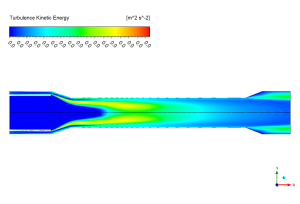
Figure 4: Turbulence kinetic energy distribution in the Jet Pump CFD analysis, highlighting the mixing region where momentum transfer occurs.


Reviews
There are no reviews yet.