


In this Transformer Radiator Cooling CFD tutorial, we provide a complete training guide on designing cooling systems for power transformers. Inside a transformer, the electrical windings generate massive heat. If this heat is not removed, the equipment can fail. While some systems use natural buoyancy, many modern designs use pumps to force the oil through. Designing these systems is challenging because the oil’s behavior changes as it cools: it becomes thicker and stickier (higher viscosity). Engineers use ANSYS Fluent to simulate this complex behavior. This Transformer Radiator cooling fluent simulation helps manufacturers ensure the oil temperature stays below the safety limit of 105°C without building expensive physical prototypes.
In this lesson, we perform a detailed thermal simulation of a single radiator panel. Unlike simple water cooling, we focus on Variable Viscosity flow. We set the inlet velocity to 0.61 m/s to simulate the pump. By following this Transformer Radiator Cooling CFD guide, you will learn how to verify if the radiator surface area is sufficient to cool the oil effectively before it returns to the tank. For more training, please explore our Heat Transfer tutorials.
- Reference [1]: Anishek, S., et al. “Performance analysis and optimization of an oil natural air natural power transformer radiator.” Procedia Technology24 (2016): 428-435.
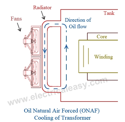
Figure 1: Schematic diagram of the ONAN System showing the natural circulation loop where hot oil rises and cool oil descends through the Transformer Radiator.
Simulation Process: Transformer Radiator Cooling CFD Setup
For this Transformer Radiator Cooling CFD study, we modeled a single radiator panel. The geometry is very thin (only 1 cm thick), which makes meshing difficult. We generated a high-quality Polyhedral Mesh with 2,151,831 cells. We chose polyhedral cells because they are very accurate for thin walls and converge faster than tetrahedral cells. We refined the mesh near the walls to capture the heat transfer boundary layer correctly.
Crucially, we defined the Oil Material Properties with a specific rule: Density is Constant, but Viscosity is Temperature-Dependent. This is the key to this Transformer Radiator Cooling CFD simulation. As the oil cools near the walls, it becomes more viscous, which affects the flow resistance. We set the Inlet Velocity to 0.61 m/s and the Inlet Temperature to 120°C. We also enabled the Discrete Ordinates (DO) Radiation Model to account for heat radiating from the hot metal to the air. We ran the simulation until the flow reached a steady state.


Figure 2: Geometry and Mesh of the radiator model, showing the thin panel design and the high-quality Polyhedral mesh used for the ANSYS Fluent simulation.
Post-processing: Transformer Radiator Cooling CFD Analysis
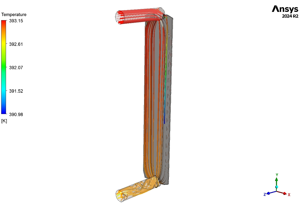
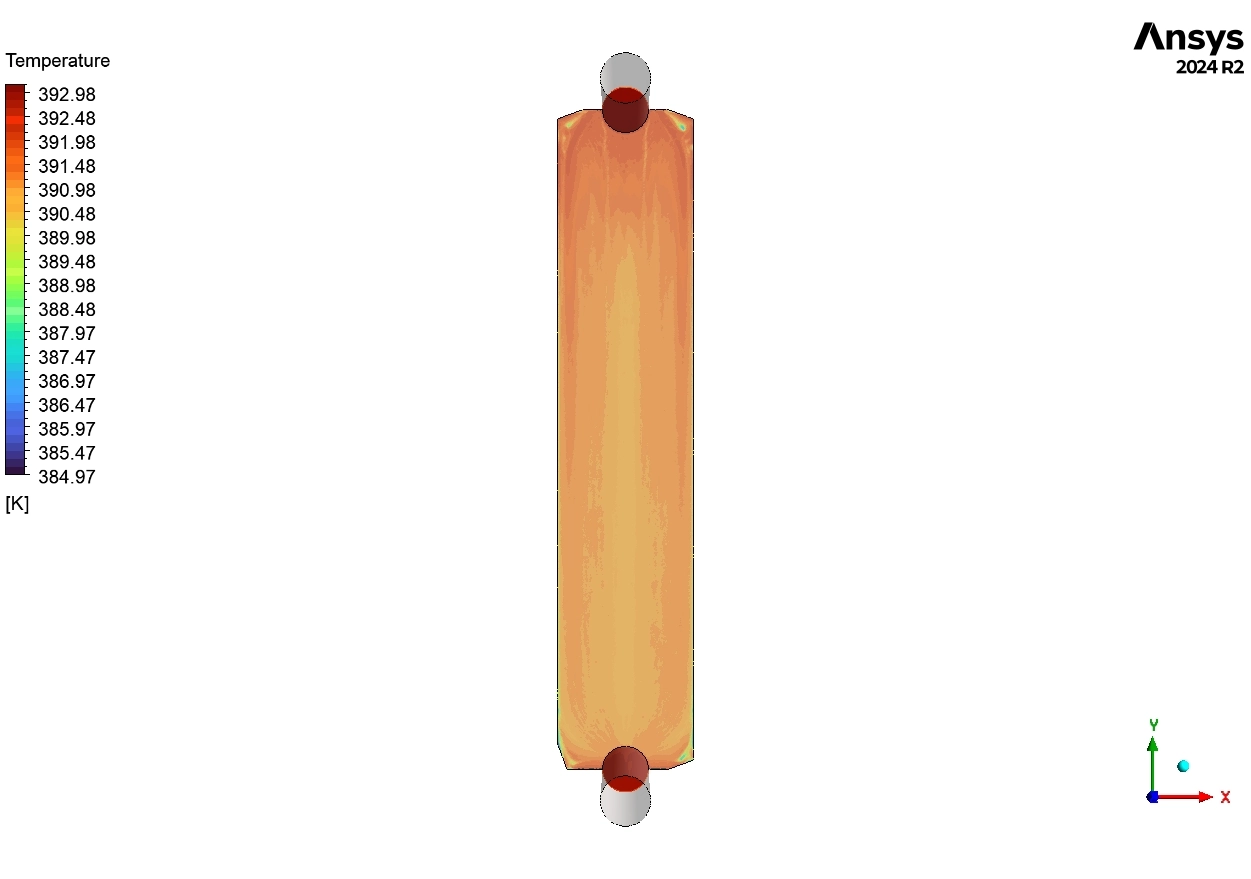
This section analyzes the engineering data to evaluate the Transformer Radiator Cooling CFD results. We interpret the contours to help designers improve the system. First, we analyze the Temperature Streamlines in Figure 3. The oil enters at the top at 120°C. As it flows down, the color changes very slightly. The average Outlet Temperature is 119.67°C. This means the temperature drop is only 0.33°C. From an engineering perspective, this is a poor result. It indicates that the 0.61 m/s inlet velocity is too high. The oil rushes through the radiator so fast that it does not have enough “residence time” to release its heat to the air.
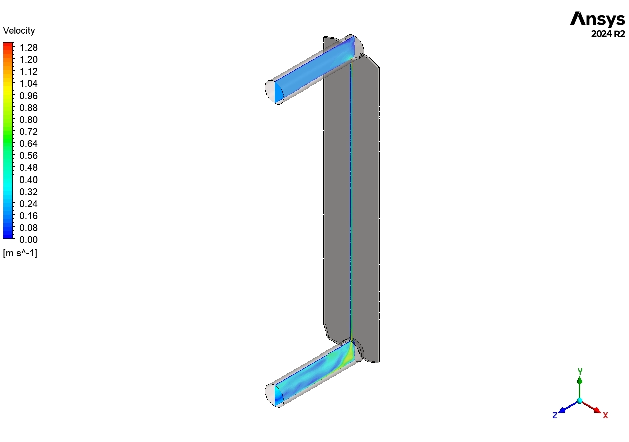
Next, we examine the Velocity Field in Figure 5. The maximum velocity is 1.31 m/s at the inlet pipe. Inside the panel, the speed settles around 0.5 – 0.7 m/s. This confirms our diagnosis. In a cooling system, we usually want slower flow to allow better heat transfer. This high speed explains why the temperature drop was only 0.33°C. The variable viscosity did not slow the flow enough to make a difference because the pump pressure was too strong.

Figure 3: Temperature Streamlines inside the oil volume, tracing the path from the 120°C inlet (Red) to the outlet showing a minimal temperature drop.
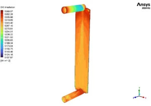
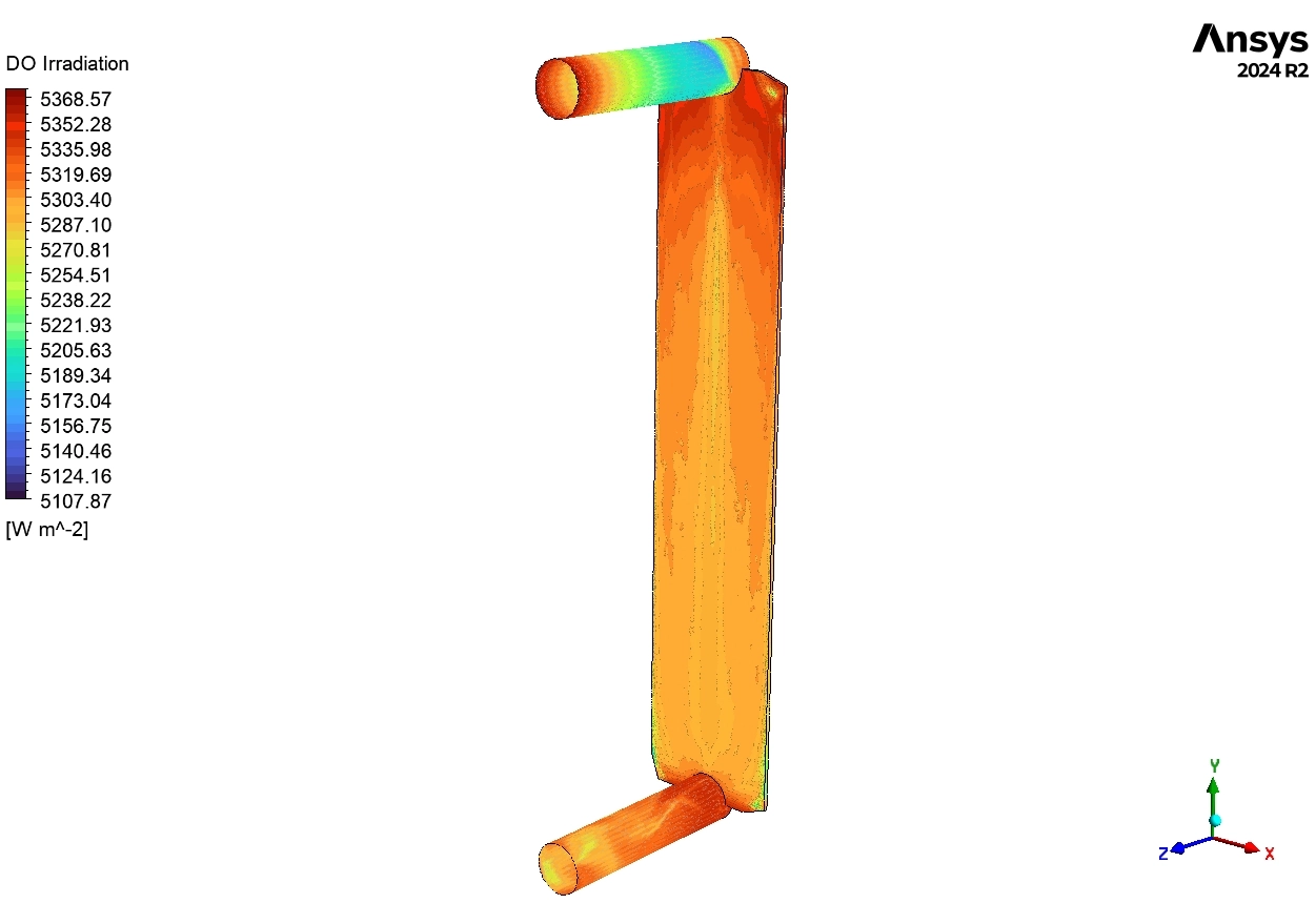
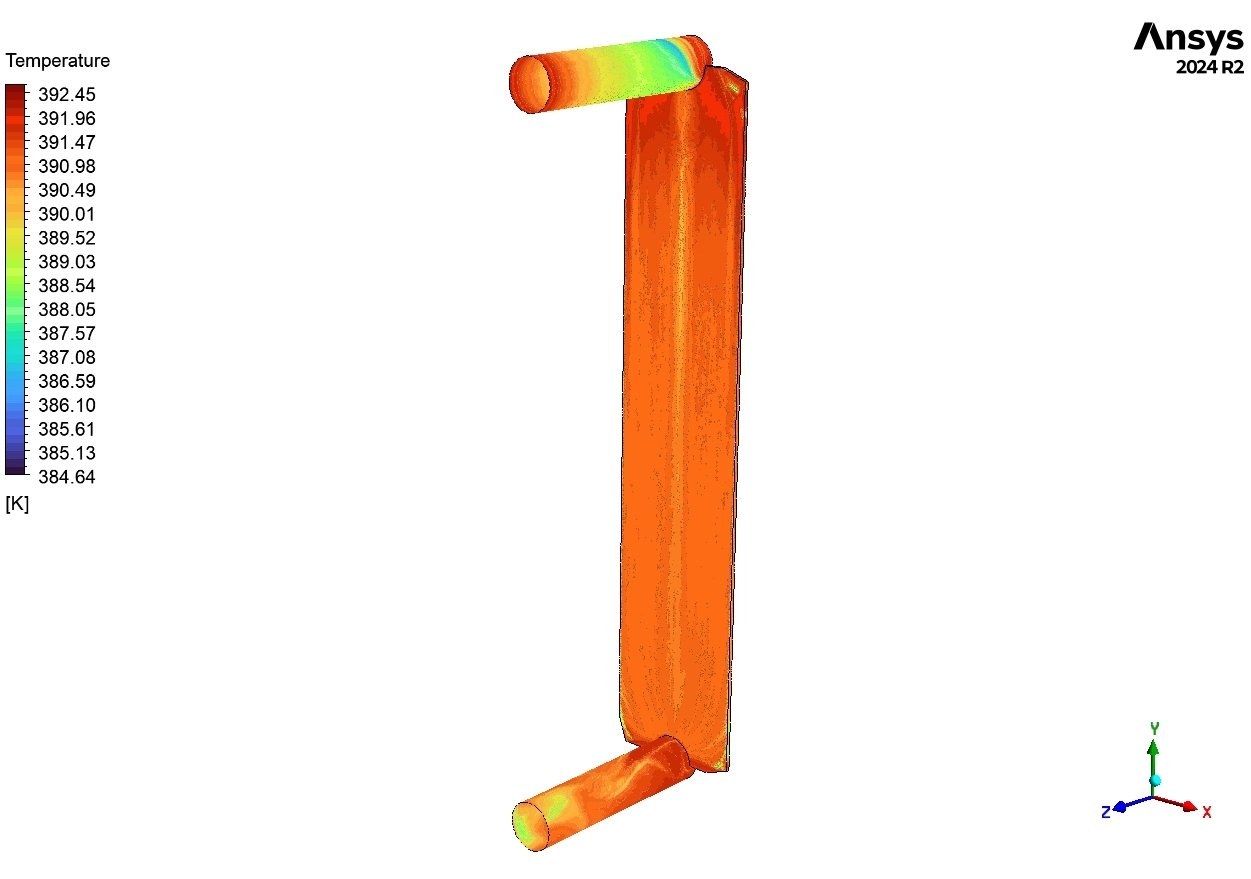
Figure 4: Radiation Heat Flux Contour (DO Model) on the radiator walls, showing high heat emission (Red, ~5368 W/m²) at the top where oil is hottest.
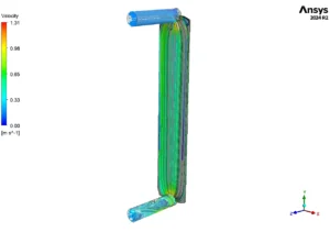
Figure 5: Velocity Magnitude Streamlines showing the forced oil flow speed, with maximum velocity (Red, 1.31 m/s) driven by the pump.
Finally, we look at the Radiation Heat Flux in Figure 4. The contour shows values around 5368 W/m² at the top. The top is Red because the oil is hottest there, and radiation depends on temperature. This proves that the DO Radiation Model is working correctly. However, even with radiation, the cooling is not enough. This Transformer Radiator Cooling CFD analysis proves that the designer needs to either lower the pump speed (to increase residence time) or add fins to the radiator to increase the surface area.


Reviews
There are no reviews yet.