
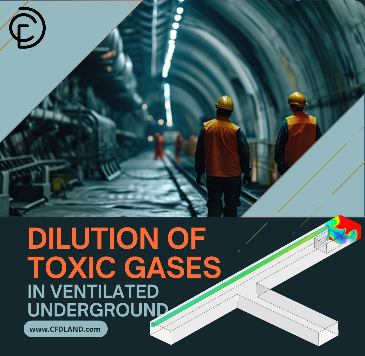
Underground mining and tunneling are high-risk environments where safety is the number one priority. During excavation or blasting, dangerous gases like Carbon Monoxide (CO) or Methane (CH4) are released. If these gases are not removed quickly, they can poison workers or cause massive explosions. To prevent this, engineers use powerful ventilation systems to blow fresh air into the tunnel. This process mixes the fresh air with the bad gas, lowering its concentration to a safe level. This is known as the Dilution of Toxic Gases in Ventilated Underground environments.
This project is a Dilution of Toxic Gases in Ventilated Underground CFD simulation designed to teach you how to predict airflow and safety. It is important to clarify that this is a CFD simulation, not a validation study. We use ANSYS Fluent to visualize the invisible gas clouds and check if the fans are strong enough. This allows us to test dangerous scenarios without putting anyone at risk. For more examples of air quality control, please visit our HVAC tutorials.
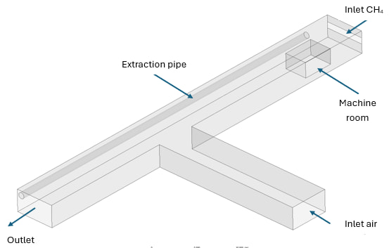
Figure 1: Layout of the underground tunnel showing the horizontal drift and vertical exhaust shaft.
Simulation Process: Species Transport and Polyhedral Meshing
To start this Dilution of Toxic Gases fluent tutorial, we first built the tunnel geometry. It features a horizontal section where the work happens and a vertical shaft that creates a sharp 90-degree turn. Ideally, we want to simulate how gas moves through this complex shape. The most important step was creating the mesh. We used ANSYS Fluent Meshing to generate a Polyhedral mesh containing 366,594 cells. We chose polyhedral cells because they are excellent for mining tunnels. They fit irregular rock walls better than square cells and calculate the results faster.
In the ANSYS Fluent setup, we turned on the Species Transport model. This is the specific tool used for Dilution of Toxic Gases Heat Sink ANSYS fluent studies because it tracks different gases separately. We defined a mixture of Air (Oxygen/Nitrogen) and Methane (CH4).
Post-processing: Analysis of Gas Dispersion and Velocity Dead Zones
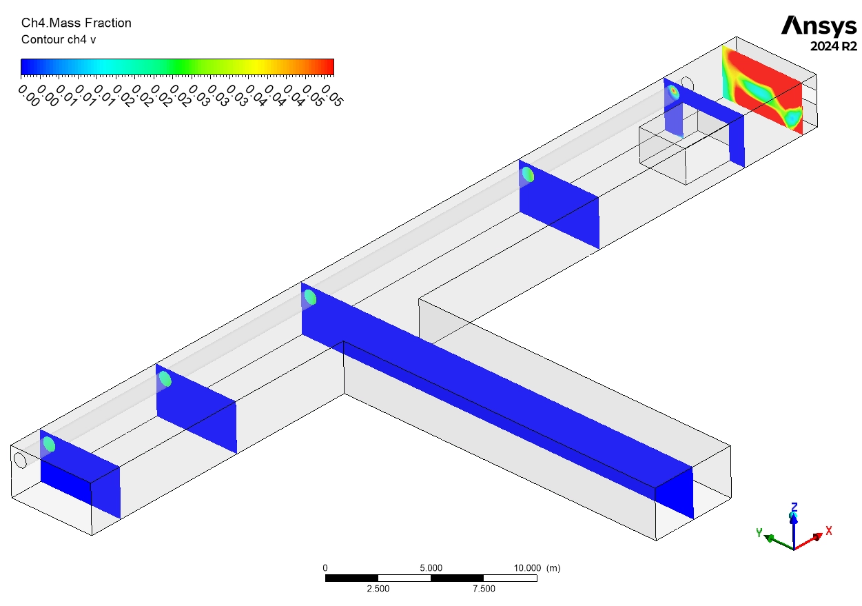
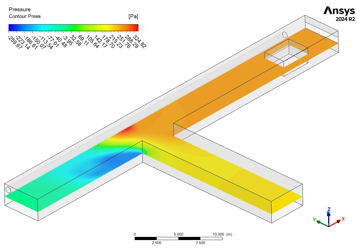
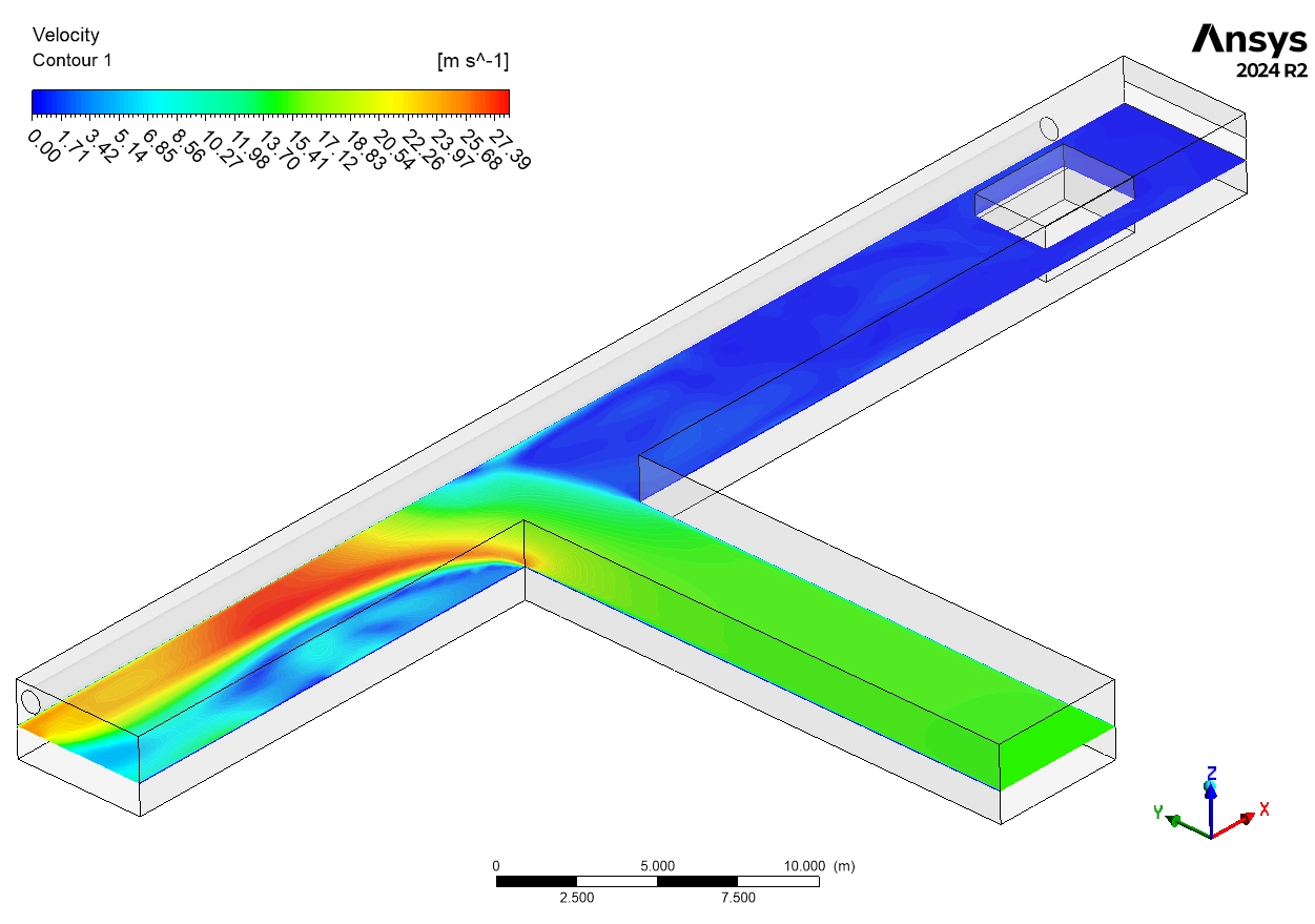
An analysis of the Dilution of Toxic Gases in Ventilated Underground results reveals critical safety insights that can only be seen through simulation. We begin by analyzing the flow dynamics shown in the velocity contours. The fresh air enters the horizontal tunnel at a moderate and safe speed of 10 to 15 m/s. However, the physics changes dramatically as the air reaches the corner to exit up the vertical shaft. The velocity contour shows a massive spike in speed, reaching 20 to 27 m/s. This acceleration is explained by the Continuity Equation. As the air is forced to turn the sharp 90-degree corner, the effective path gets smaller, so the air must speed up to squeeze through. While high speed usually helps remove gas, the air then decelerates rapidly to 8-12 m/s as it expands into the vertical shaft. This fluctuation in speed creates a complex pressure environment that directly impacts how well the gas is removed.
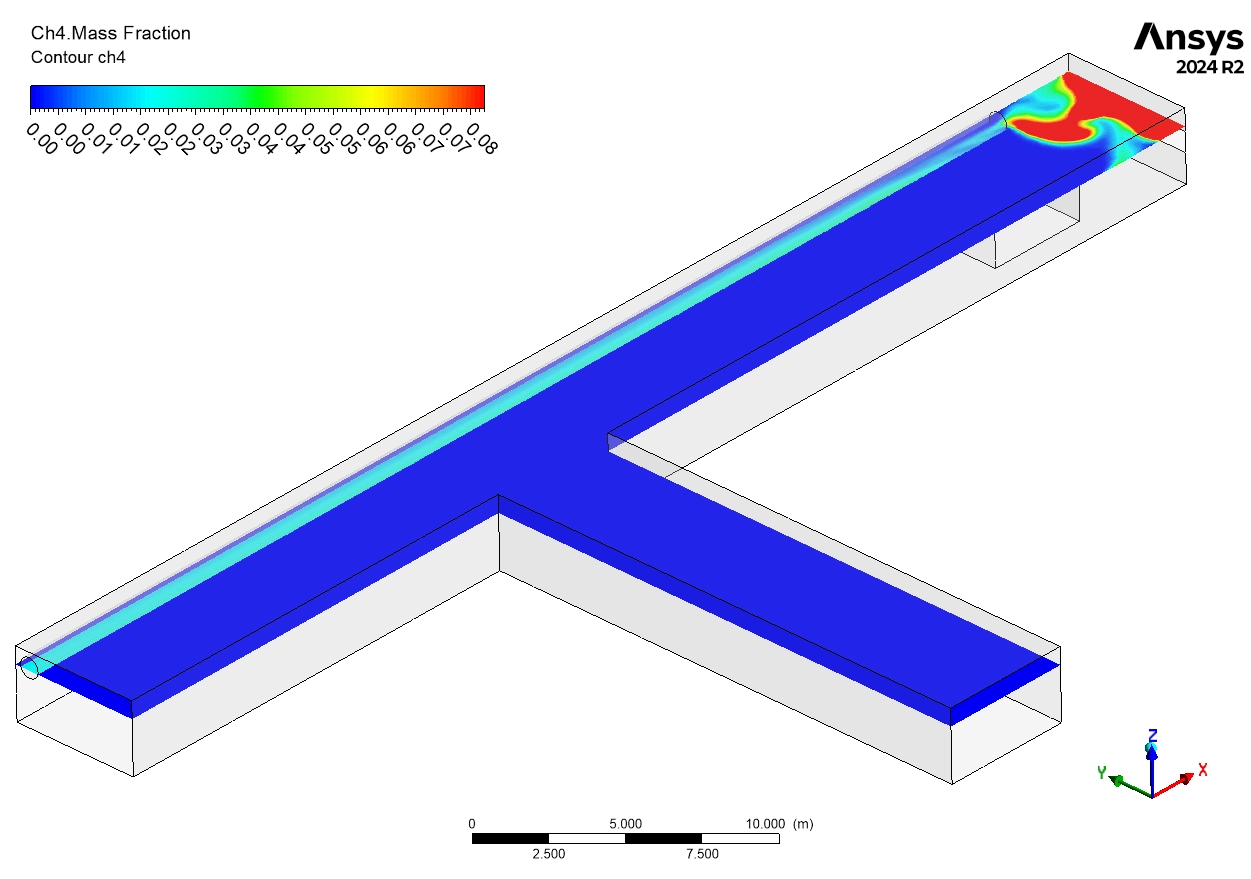
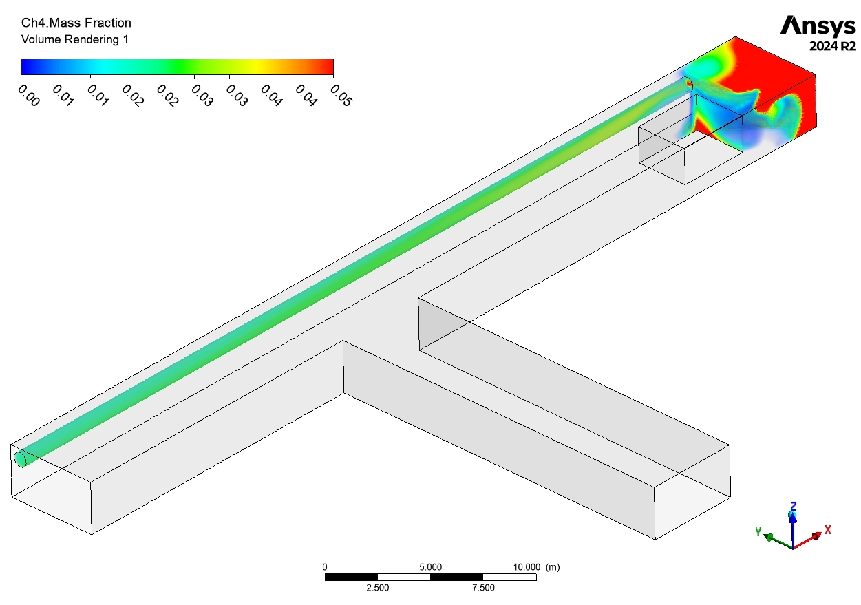
The most critical part of this Dilution of Toxic Gases in Ventilated Underground Simulation is the Methane (CH4) analysis. The contours show the Dead End of the tunnel, which is the farthest point from the fresh air supply. At the specific release point in this dead end, we see an intense Red Cloud. The simulation data indicates the Methane concentration here is between 4% and 5%. This is a flashing red warning for engineers because Methane becomes explosive at a concentration of 5%. This proves that the dead-end zone is a high-risk area where gas accumulates because the airflow is too weak to push it out immediately. As the ventilation air hits the edge of this cloud, the dilution process begins. We can visually track the mixing as the contour colors shift from Red to Yellow-Orange (2-3%) and finally to Green (1%). This confirms that the ventilation system is successfully breaking apart the concentrated toxic cloud and rendering it safer as it moves down the tunnel.
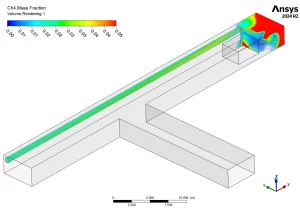

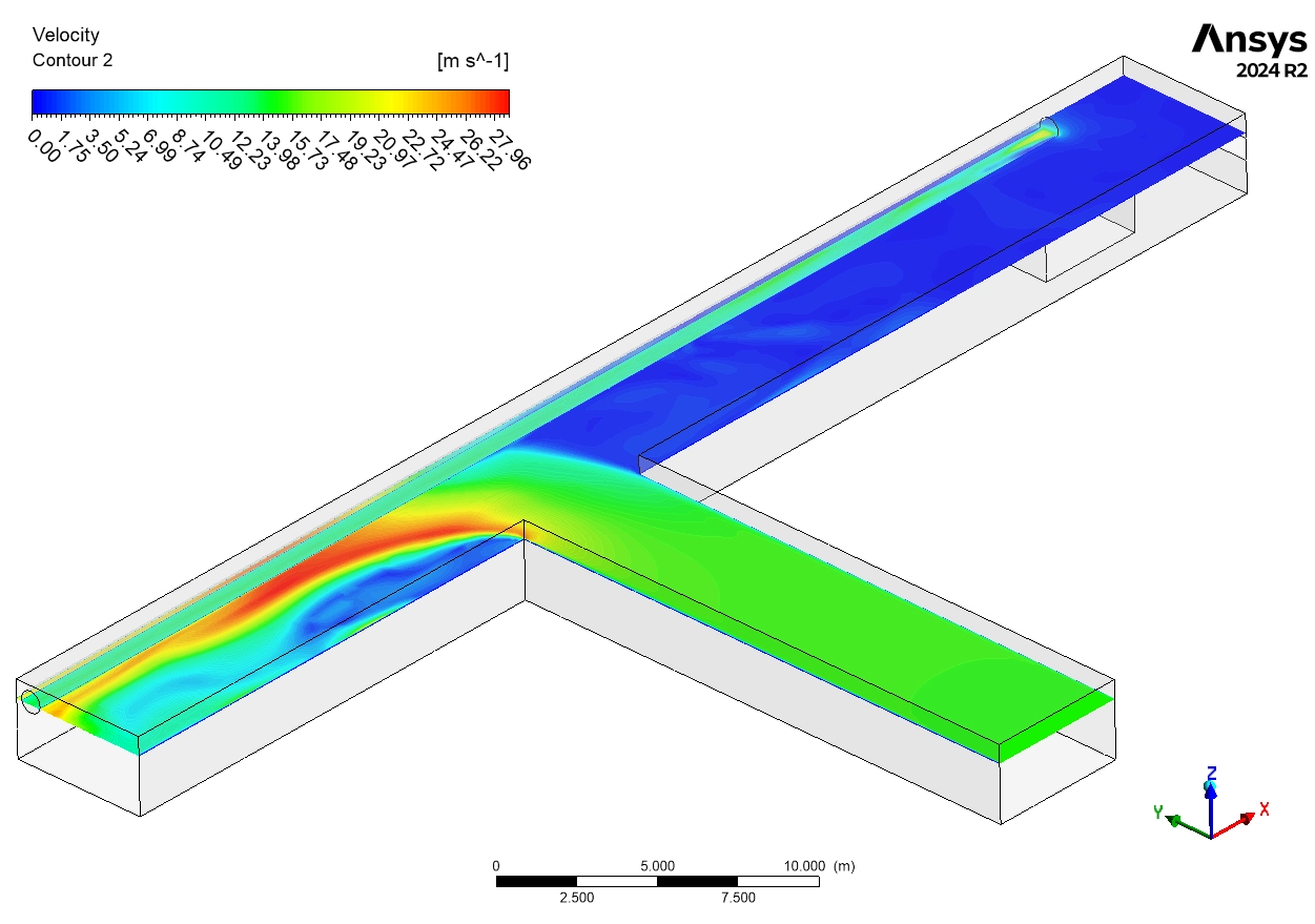
Figure 3: CH4 Mass Fraction and Velocity contours showing the gas trap at the corner.
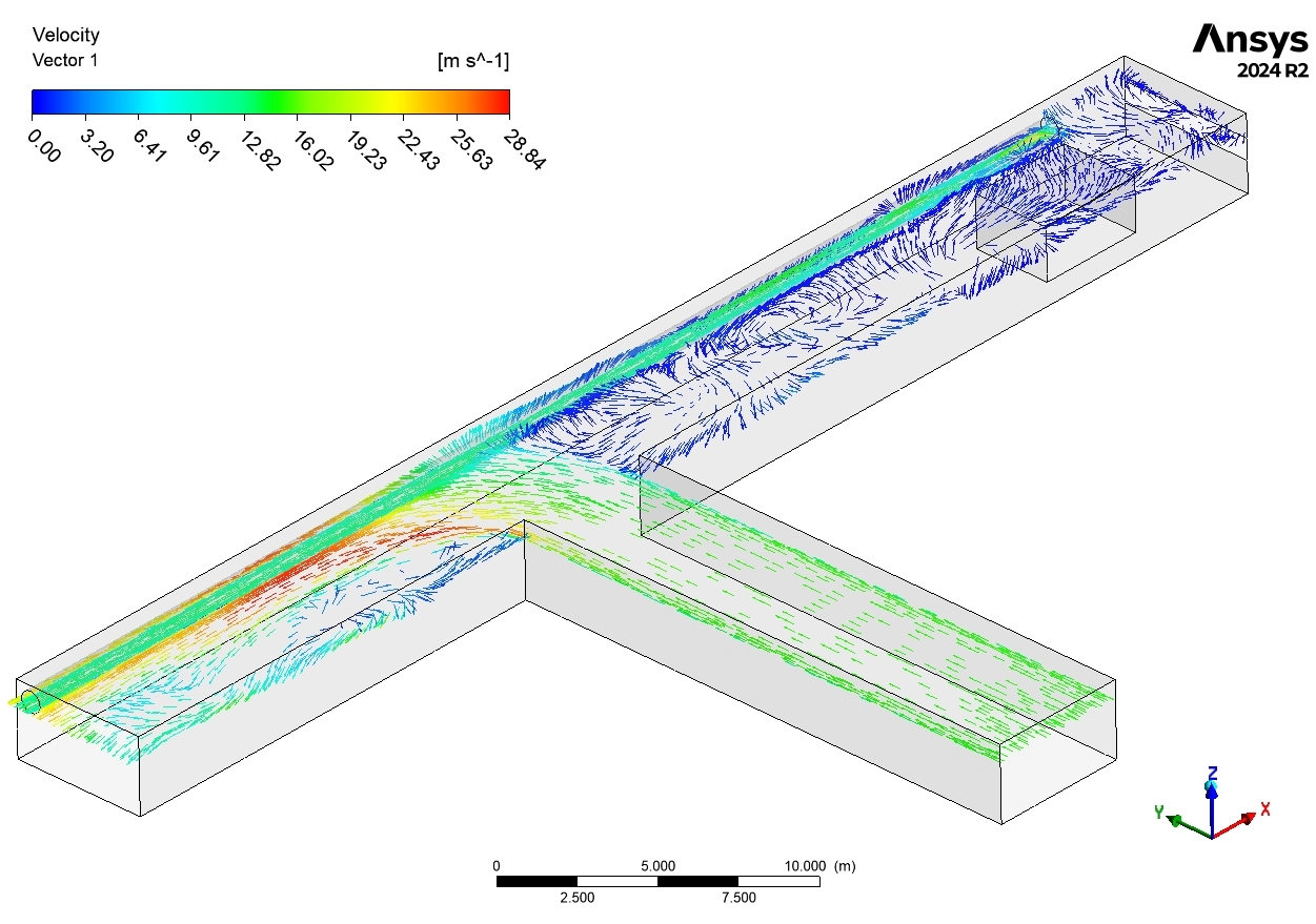
However, a deeper look at the corner geometry reveals a hidden danger. Even though the air velocity is highest at the corner (27 m/s), the Methane contour remains Yellow-Green, indicating a concentration of 1-2%. This seems contradictory—why is there gas where the air is fastest? The answer lies in the shape of the turn. The sharp 90-degree angle creates a “Recirculation Zone” or a swirl trap. The main airflow shoots around the corner so fast that it detaches from the wall, creating a pocket of swirling, stagnant air behind it. The toxic gas gets trapped in this swirl and cannot escape up the shaft easily. This is a vital finding from the Dilution of Toxic Gases Heat Sink ANSYS fluent study. It tells the designer that simply increasing fan power is not enough. To fix this, they must modify the tunnel geometry by rounding the corner or installing a small “booster fan” to flush out that specific recirculation pocket.
Key Takeaways & FAQ
- Q: Why is the 5% Methane level critical?
- A: 5% is the Lower Explosive Limit (LEL) of Methane. If the concentration reaches this level, a single spark can cause an explosion. The simulation identified a 4-5% zone in the dead end, marking it as a danger zone.
- Q: What is a Recirculation Zone?
- A: As shown in the corner analysis, a recirculation zone is a swirling pocket of air formed when fast airflow separates from a sharp wall. In this Dilution of Toxic Gases study, it trapped 1-2% of the toxic gas, preventing it from leaving the tunnel.


Reviews
There are no reviews yet.