


An Erosion In A Bent Pipe CFD simulation is a crucial tool for industries like oil and gas, mining, and power generation, where fluids containing solid particles (like sand, catalyst, or ash) are transported through pipelines. When the pipe changes direction, such as in an elbow or bend, these solid particles can wear away the pipe wall, leading to leaks and failures. This report details a CFD simulation using ANSYS Fluent that precisely predicts where this damage will occur and how severe it will be.
This powerful multiphase simulation technique is a great example of the skills taught in our comprehensive ANSYS Fluent course for beginners, a Course that provides an excellent foundation for performing your own industrial simulations.
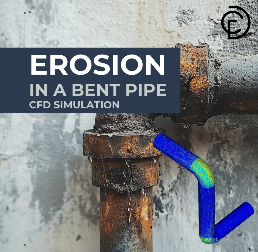
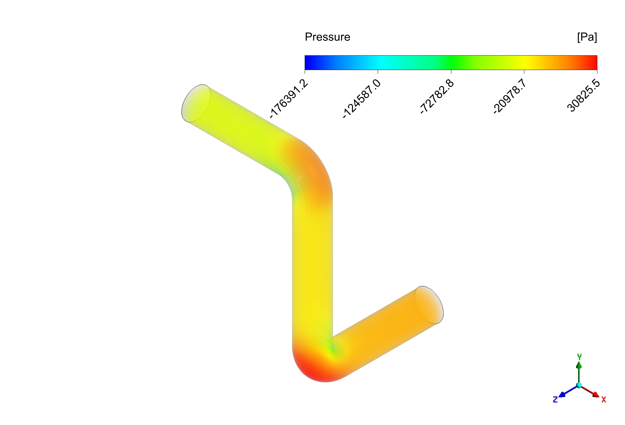
Figure 1: Erosion inside a bent pipe CFD Simulation Using DPM
Simulation Process: Modeling Erosion with the DPM in Fluent
The simulation was performed using a 3D model of a standard pipe bend. To accurately simulate this Erosion DPM Fluent problem, a two-part approach is needed:1. Continuous Phase: The fluid (like water or gas) is modeled using standard fluid dynamics equations and a turbulence model like k-epsilon to capture the swirling flow inside the pipe. 2. Discrete Phase: The solid particles are modeled using the Discrete Phase Model (DPM). This powerful tool tracks thousands of individual particle “parcels” as they travel through the fluid. Most importantly, Fluent’s built-in Erosion Model is activated. This model uses the information from the DPM—like the speed, angle, and number of particle impacts on the wall—to calculate the rate of material loss (erosion) on the pipe surface.
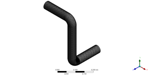
Figure 2: Hexagonal cells spread over Bent pipe
Post-processing: CFD Analysis, How Inertia Causes Concentrated Wall Damage
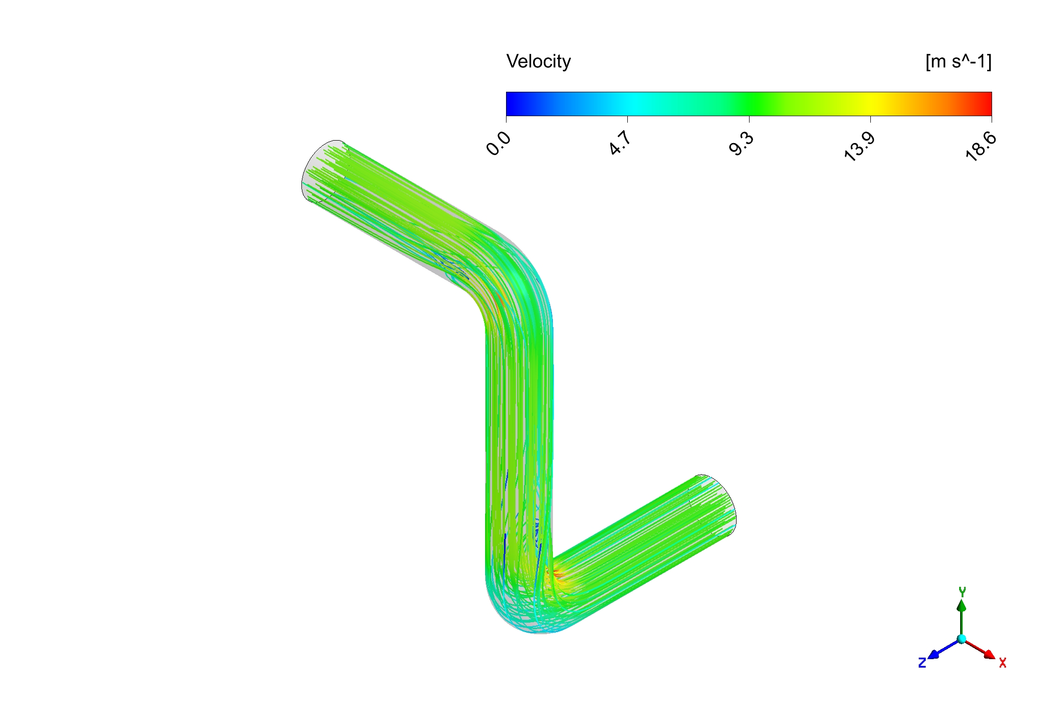
The simulation results provide a clear and fully substantiated story that begins with the pipe bend, which is the primary “cause” of the erosion problem. As the fluid flows smoothly around the bend, it easily changes direction. However, the solid particles suspended within the fluid are much heavier and have more inertia. The direct “effect” of this inertia is that the particles cannot follow the fluid’s curved path. Instead, they tend to continue in a straighter line, separating from the main flow and flying toward the outer wall of the bend. The particle tracks plot in Figure 2 is the perfect visual proof of this phenomenon. It clearly shows the particle trajectories deviating from the fluid streamlines and concentrating their impacts on a specific, focused area of the outer pipe bend.
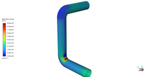

Figure 3) a) shear stress b) pressure gradient inside the elbow
These concentrated particle impacts are the “cause” of the next critical effect: localized and accelerated wear of the pipe wall. Each particle impact acts like a tiny sandblasting event, chipping away a microscopic amount of material. When millions of particles strike the same small area, the cumulative “effect” is a significant and predictable pattern of erosion. The erosion rate contour in Figure 1 is the definitive proof of this. The area of maximum erosion (shown in red) corresponds exactly to the location where the particle tracks in Figure 2 showed the highest concentration of impacts. This directly links the cause (particle inertia) to the final effect (material loss). The most significant achievement of this Erosion DPM CFD analysis is the clear demonstration of how the bend in the pipe (the cause) forces heavy particles, due to their inertia, to strike the outer wall, which in turn causes highly localized material erosion (the effect). This validated CFD model gives engineers a powerful predictive tool to identify high-wear zones before they fail, allowing them to reinforce critical areas, use more resistant materials, or optimize the pipe design to extend the service life of critical industrial equipment.
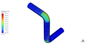
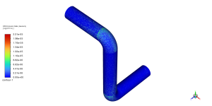
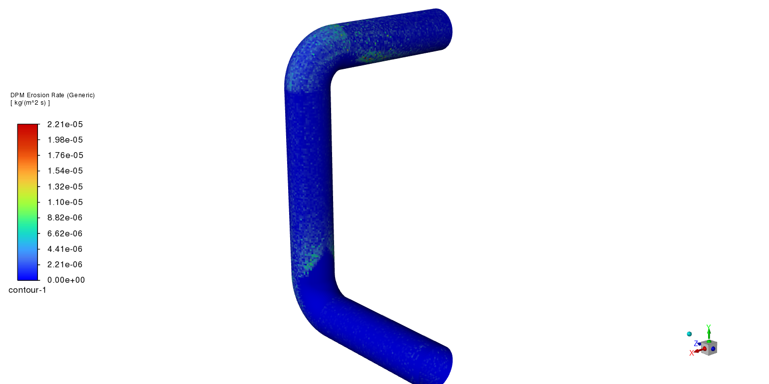
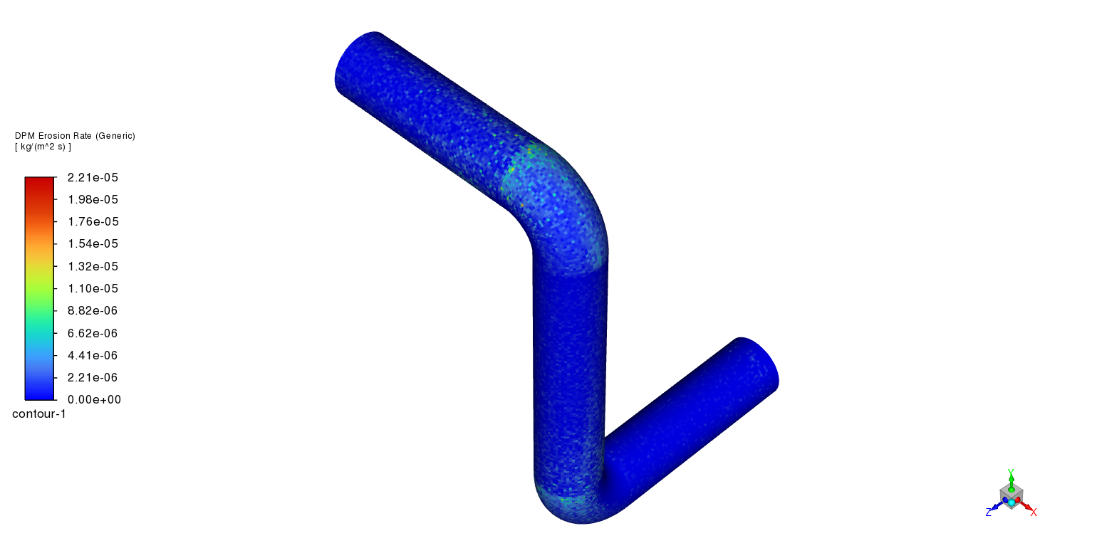
Figure 4: Contour plot from the Erosion In A Bent Pipe Fluent simulation, showing the DPM erosion rate. The red area indicates the location of the most severe material loss.


2 reviews for Erosion in a Bent Pipe CFD: A FREE Fluent DPM Tutorial
Daniel Sami (verified owner) –
Looks like a nice TUTORIAL
Mech –
good