


A flat plate with fins is a very common physical tool used to protect machines. Engineers use these metal heat sinks to rapidly cool down hot electronic chips, car radiators, and air conditioners. The thin vertical metal fins greatly increase the outer surface area of the device. This large surface area helps the dangerous heat escape from the hot engine into the surrounding cold air. However, mathematically predicting how the invisible heat flows through the solid metal and into the moving air is extremely difficult. Therefore, smart designers use a highly accurate Flat Plate With Fins Heat Transfer CFD Simulation to perfectly see the thermal physics. By practicing this Ansys Fluent tutorial project, engineers can safely test different fin designs without building expensive broken prototypes. This computational representation solves complex energy equations to find the exact thermal resistance of the whole system. To learn more about how engineering software calculates hot moving fluids and cooling metals, please explore our professional Heat Transfer category. A detailed CFD analysis helps factories optimize the metal thickness and spacing to achieve the maximum possible cooling performance.
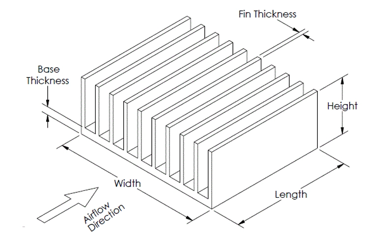
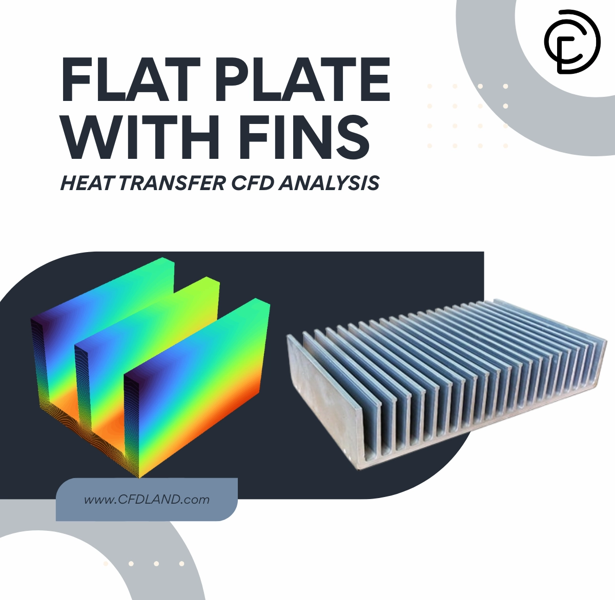
Figure 1: Schematic diagram of the flat plate with fins, showing the basic physical shape and the direction of the cooling airflow.
Simulation Process: Conjugate Heat Transfer Setup
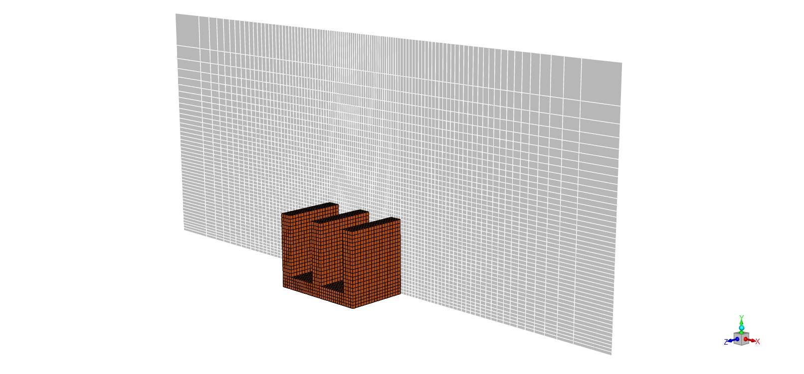
For this electronics cooling project, we built a precise 3D geometry of a flat aluminum base plate carrying three vertical fins. We used the ANSYS ICEM CFD software to create a highly structured hexahedral mesh. This high-quality mesh contains exactly 830,790 cells. We specifically placed very small, fine cells near the solid metal walls to perfectly capture the thin thermal boundary layers. Next, we imported this mesh into ANSYS Fluent to consider the Conjugate Heat Transfer (CHT) method. This powerful method mathematically calculates the solid aluminum conduction and the flowing air convection at the exact same time.
Inside the software, we applied a heavy, constant heat flux of exactly 3000 W/m² to the bottom floor of the base plate. This perfectly simulates the heavy heat load coming from a working computer CPU. To simulate a forced convection cooling fan, we injected fresh air into the channel at a steady inlet velocity of exactly 0.2 m/s (20 cm/s).

Figure 2: Structured hexahedral grid generated in ANSYS ICEM CFD, containing exactly 830,790 cells to properly capture the boundary layers.
Post-processing: Analysis of Forced Convection and Thermal Gradients
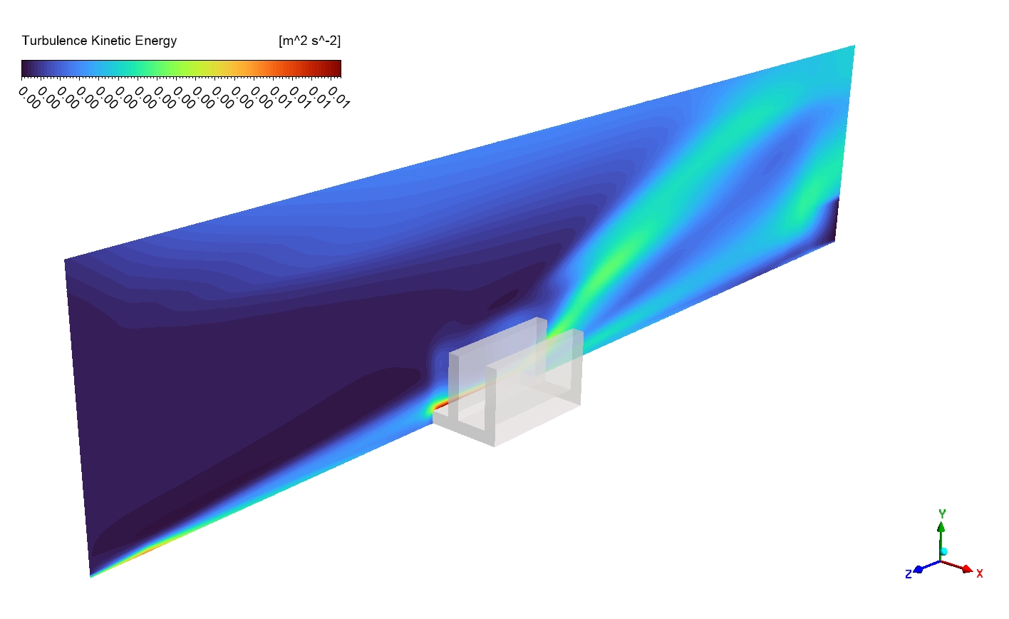
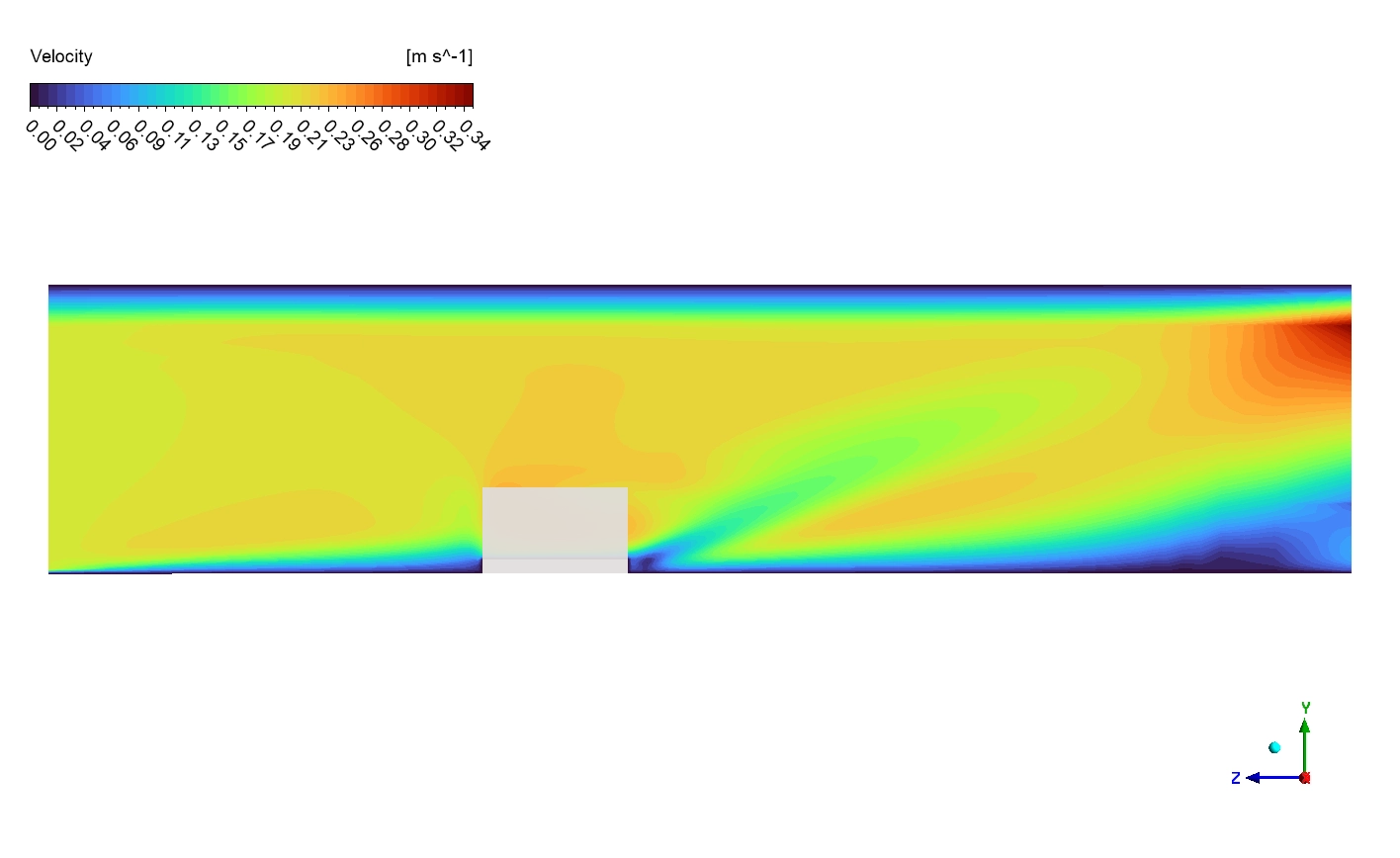
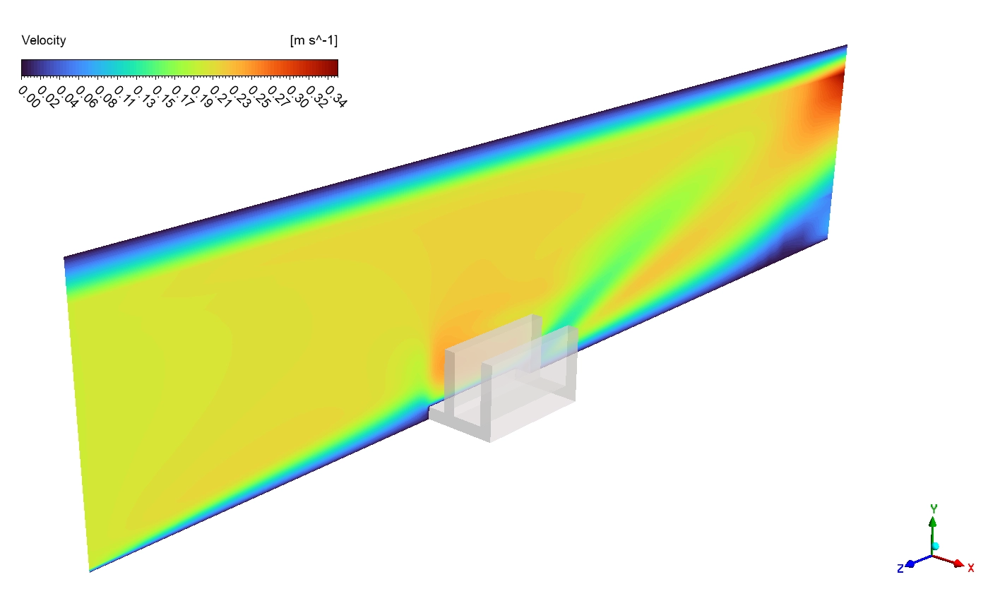
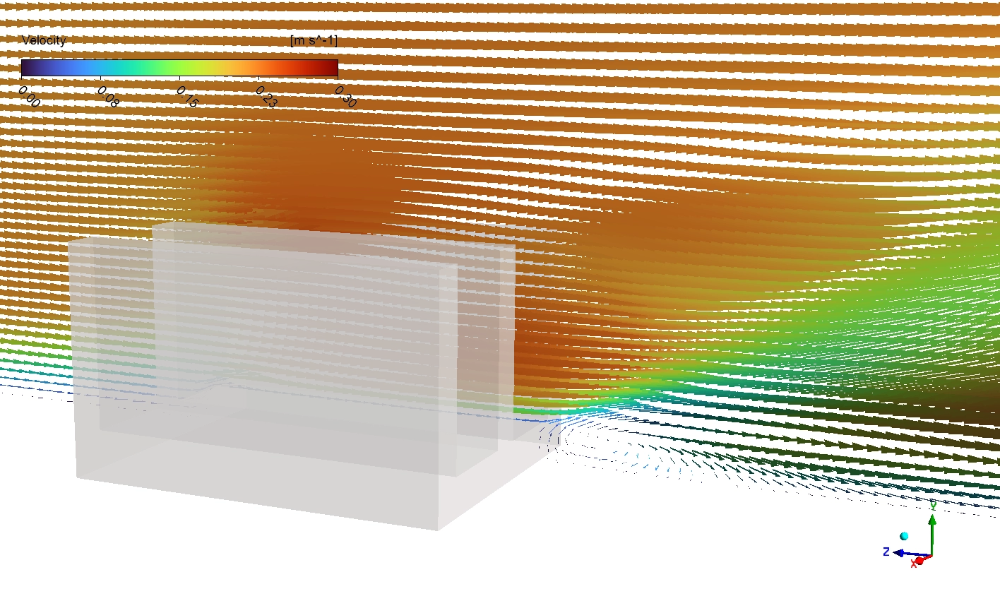
Let us carefully and deeply analyze the exact velocity and temperature contours to understand the true cooling power. First, we examine the Velocity Magnitude contour. The fresh air enters the system from the left side at a smooth, uniform speed of 0.2 m/s, shown in a dark blue color. However, when this air squeezes through the narrow gaps between the three metal fins, it mathematically accelerates. The velocity rapidly increases to a green and yellow speed of 0.25 to 0.30 m/s. This fast air is a massive engineering achievement because higher speeds create a much stronger convective heat transfer coefficient. Directly behind the fins, we clearly see small red and orange swirling circles. These are recirculation wake zones where the air moves very slowly due to the physical blockage.
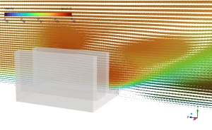
Figure 3: Velocity vector with vector overlay, highlighting the slow 0.2 m/s inlet air accelerating to 0.30 m/s between the fins.
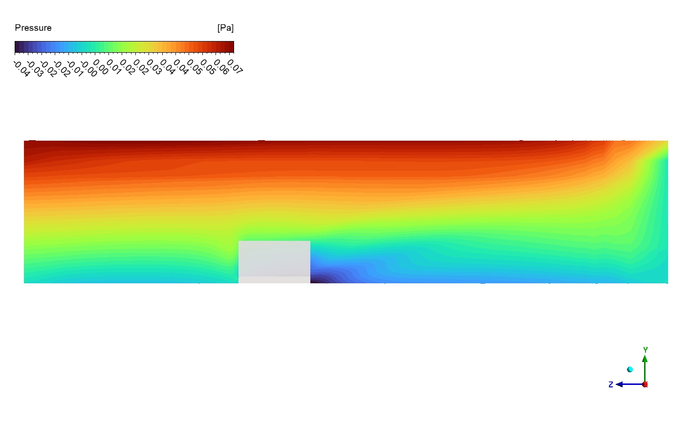
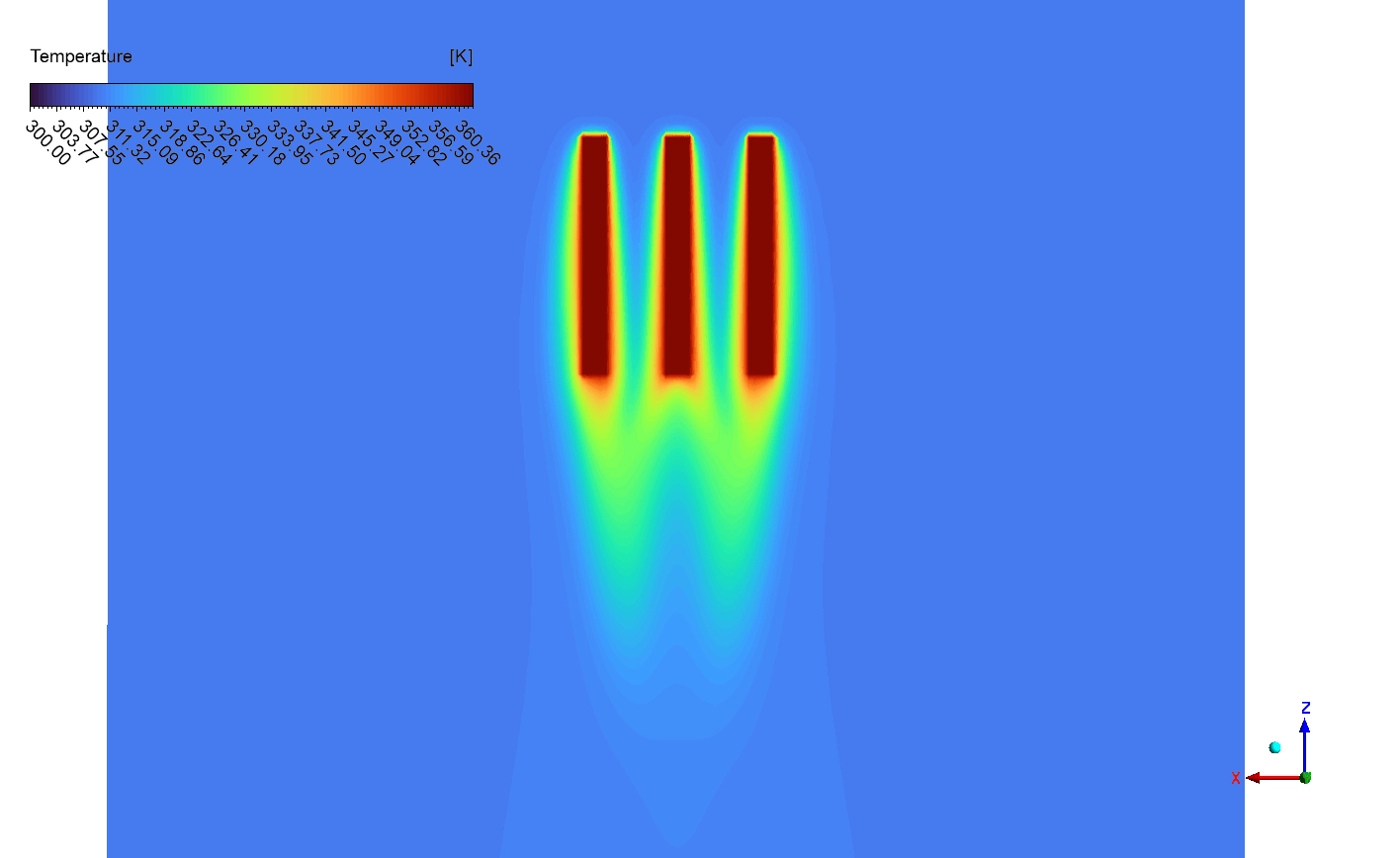
Next, we study the exact Temperature contours on the symmetry plane. The bottom base plate receives the heavy 3000 W/m² heat load and becomes extremely hot, reaching a dark red maximum of 370 to 380 K. The heat successfully conducts upward through the three fins. Because the heat travels up, the bottom of the fins stays hot at 350 to 365 K (orange and yellow), while the top fin tips become much cooler at 320 to 330 K (cyan and green). This massive vertical color change proves that the fins have significant thermal resistance and are not isothermal. Finally, the cold 300 K inlet air blows over these hot fins and successfully steals the heat. As the air leaves the system, it warms up to a cyan color of 310 to 315 K, perfectly proving that the hot thermal plume is carrying the danger away.
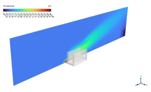
Figure 4: Side-view cross-section temperature distribution, revealing the extremely thin thermal boundary layer where heat jumps from the solid aluminum into the cold air.

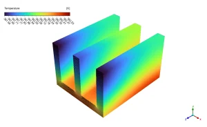
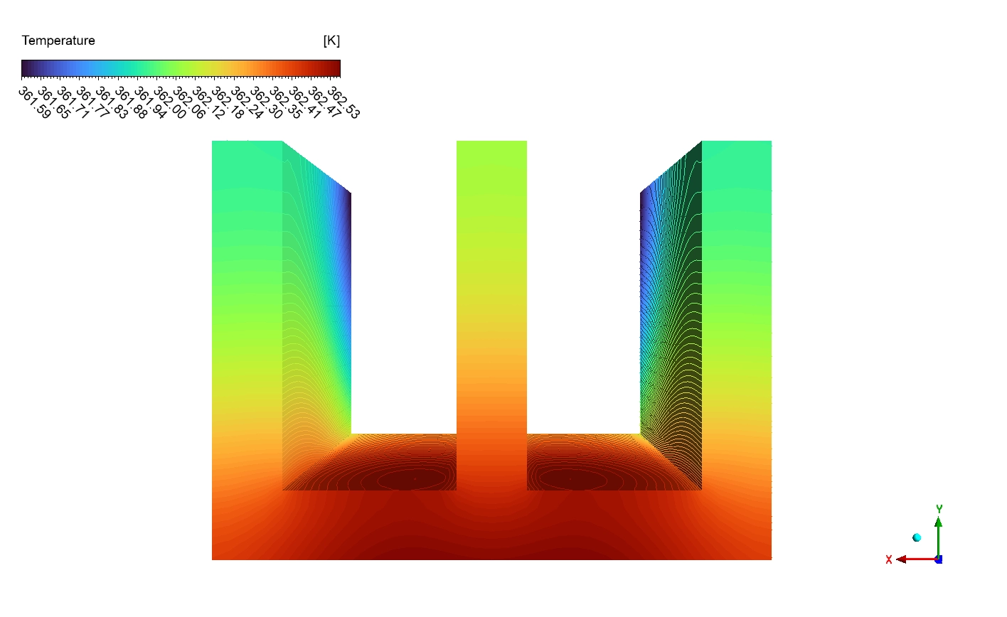
Figure 5: Isolated fin temperature contours, mathematically proving the strong vertical thermal gradient from the hot 370 K base to the cool 320 K tips.
Finally, we mathematically evaluate the overall system performance. The CFD simulation calculates that the volume-weighted average static temperature of the entire solid aluminum is exactly 362.17 K (89.02°C). When we look closely at the top-view thermal contours, we discover a highly important design insight.
Downstream of the fins, the velocity vectors show clear recirculation zones (small swirling patterns) directly behind each fin, which is typical of bluff body flow at moderate Reynolds numbers. These wake zones have lower velocity and create some thermal inefficiency, but the overall forced convection pattern successfully removes heat from the fin surfaces and carries it away downstream in the hot thermal plume (visible as warmer air in later temperature plots).
Frequently Asked Questions (FAQ)
- What is Conjugate Heat Transfer (CHT) in ANSYS Fluent?
- Conjugate Heat Transfer is a highly advanced mathematical method. It allows the software to simultaneously calculate the heat moving inside the solid metal (conduction) and the heat escaping into the moving air (convection) at the exact same time.
- Why does the air velocity increase between the metal fins?
- When the steady 0.2 m/s air hits the solid fins, the open space suddenly becomes much narrower. To push the same amount of air through a smaller gap, the laws of physics force the air to accelerate up to 0.30 m/s.


Reviews
There are no reviews yet.