


In the industrial engineering sector, centrifugal pumps move massive amounts of water through piping systems. A standard centrifugal pump uses a rotating impeller to physically grab the fluid and throw it outward using centrifugal force. Surrounding this impeller is a spiral casing called a volute. The volute collects the fast-moving water and carefully slows it down to generate pressure. The total pressure energy that the pump adds to the water is called the “pump head.” By running a Head Evaluation of Centrifugal Pump with Volute fluent simulation, engineers can mathematically calculate exactly how high the pump can push the water before manufacturing the physical metal. In this ANSYS Fluent tutorial project, you will learn how to set up the rotating domains and accurately measure the hydraulic performance. To understand how rotating blades transfer energy into liquids, please explore our comprehensive Turbomachinery tutorials. By acquiring this simulation project, students and engineers will possess a fully prepared virtual geometry to practice industrial fluid mechanics.
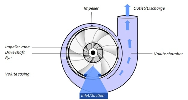
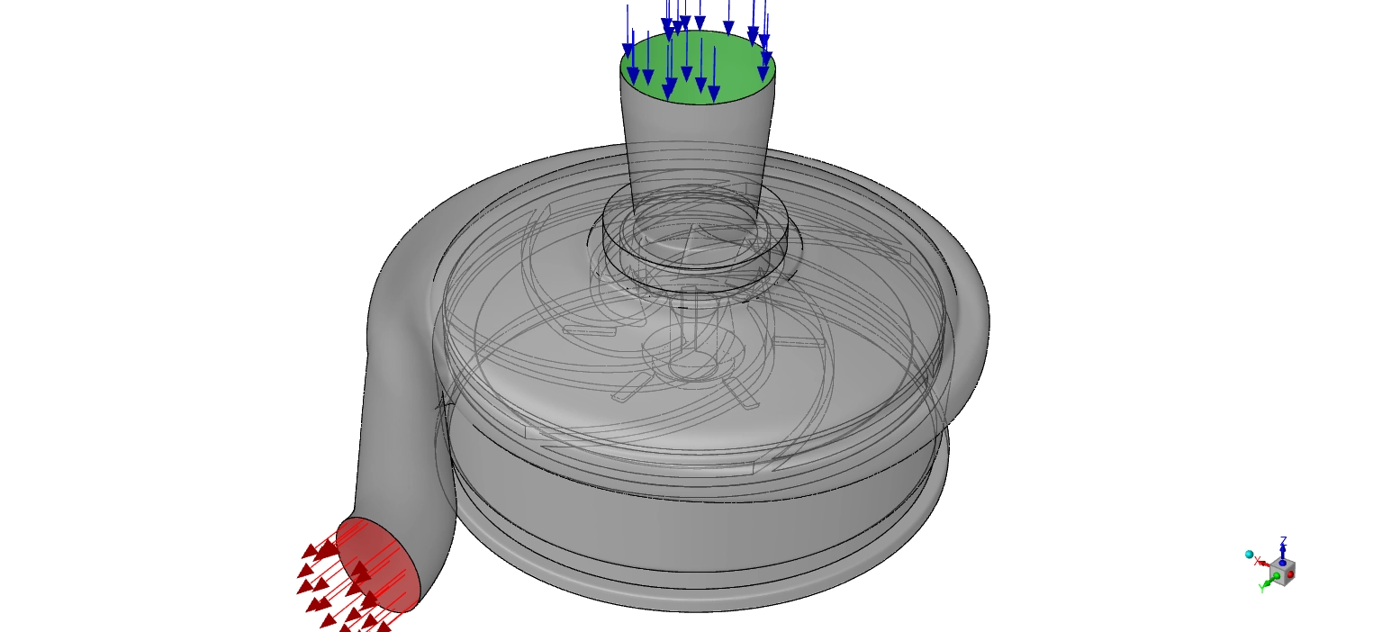
Figure 1: Structural schematic of the centrifugal pump, illustrating the rotating impeller blades and the stationary expanding volute casing.
Simulation Process: Polyhedral Meshing Strategy and Moving Reference Frame (MRF)
To perform an accurate CFD Analysis of Centrifugal Pump Head, we first imported the 3D computational representation of the pump assembly. This geometry includes the inner rotating impeller and the outer stationary volute casing. Next, the Fluent Meshing software was used to divide the fluid volume into exactly 2,548,017 polyhedral cells. Polyhedral mesh cells are highly efficient because their multiple faces capture the complex curvature of the impeller blades perfectly while keeping the calculation time low.
For the physical solver setup, we utilized the Moving Reference Frame (MRF) mathematical model. The MRF method is essential for a Head Evaluation of Centrifugal Pump with Volute ANSYS Fluent project. Instead of physically moving the mesh, the software applies a rotational velocity of 1750 rpm (revolutions per minute) to the impeller zone equations. The outer volute remains entirely stationary. This steady-state technique allows the software to accurately calculate the Coriolis and centrifugal forces acting on the water without requiring heavy computational power.

Figure 2: Computational representation of the turbomachinery geometry prepared for ANSYS Fluent, featuring 2.54 million polyhedral mesh cells.
Post-processing: Analysis of Turbomachinery Flow and Energy Conversion
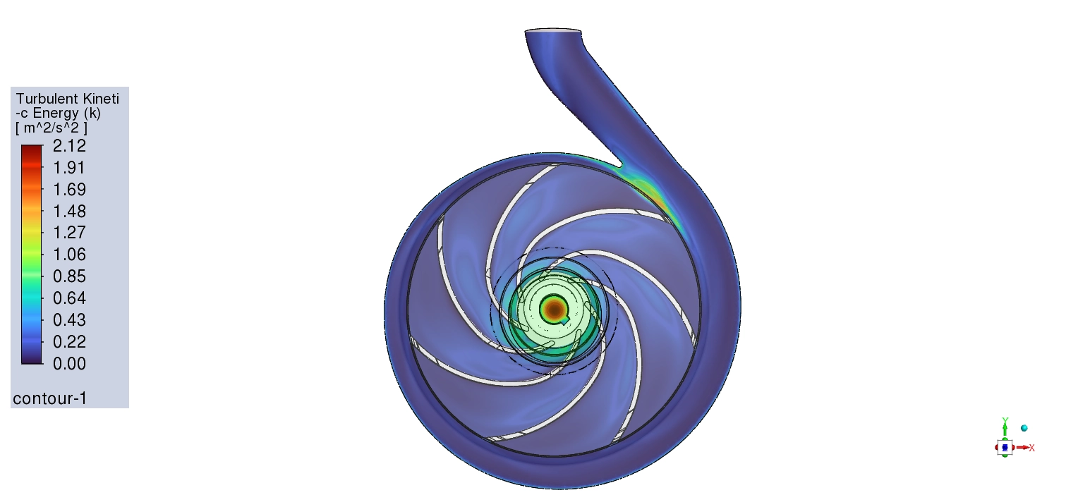
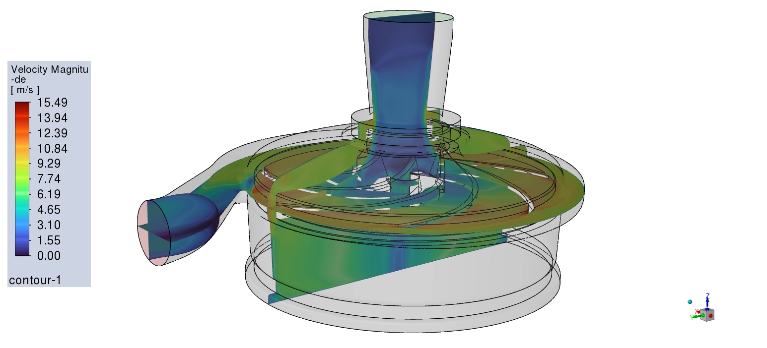
Let us carefully analyze the exact fluid mechanics driving the pump to understand how the mechanical energy turns into hydraulic pressure. The primary achievement of this Centrifugal Pump fluent simulation is the calculated total pump head of 14.177 meters. This specific number means the pump creates enough internal pressure to push a column of water vertically upward for 14.177 meters, making it highly effective for building water supply systems. To understand exactly how the geometry creates this 14.177 meters of head, we must evaluate the velocity and pressure contours together. The physics begin at the central inlet, known as the impeller eye. The pressure contour shows a very low pressure here, dropping down to 13,600 Pa. This slight suction effect is necessary to pull the incoming water into the pump. Once the water enters, the impeller blades rotating at 1750 rpm aggressively strike the fluid. The velocity contours show the water accelerating from a slow 3 to 7 m/s at the center up to an extreme peak of 15.49 m/s exactly at the outer blade tips.
Table 1: Centrifugal Pump Head Evaluation Data
| Turbomachinery Parameter | Exact Calculated Value | Unit / Equivalent |
| Impeller Rotational Speed | 1750 | rpm |
| Discharge Static Pressure Range | 118,000 to 133,000 | Pa |
| Total Pressure Rise Generated | 139,000 | Pa (1.39 bar) |
| Total Calculated Pump Head | 14.177 | Meters |

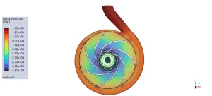
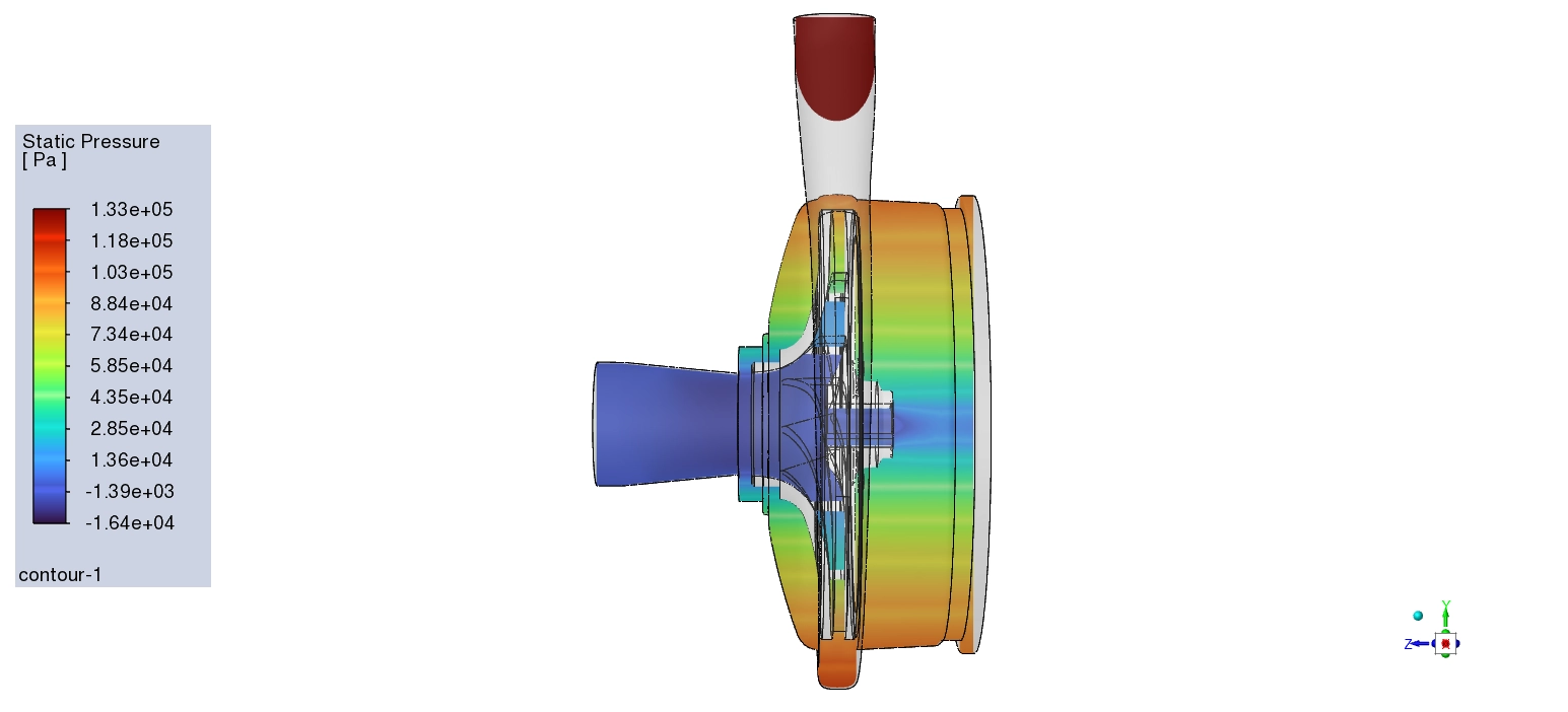
Figure 3: Static pressure distribution contours, proving the successful conversion of kinetic energy into a maximum discharge pressure of 133,000 Pa.
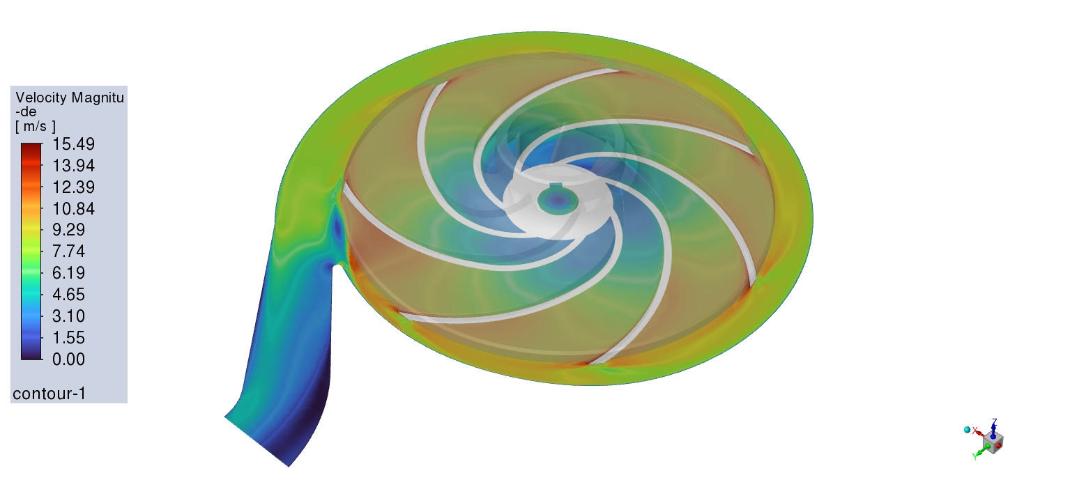
At this exact moment, the water possesses massive kinetic energy, but it does not yet have high static pressure. The true engineering success happens inside the stationary volute casing. As the highly energetic water leaves the blade tips at 15.49 m/s, it crashes into the expanding spiral shape of the volute. Because the physical cross-sectional area of the volute becomes wider toward the exit, the fluid is forced to slow down. The velocity contours visibly confirm this physics, showing the speed dropping rapidly from 15.49 m/s down to a range of 5 to 9 m/s near the discharge pipe. According to the laws of fluid dynamics, when a liquid loses kinetic energy (velocity), it must gain static energy (pressure). The pressure contours mathematically prove this energy conversion. As the flow decelerates, the static pressure climbs massively, reaching a final scale of 118,000 Pa to 133,000 Pa at the outlet nozzle. The pressure difference between the low-pressure suction eye and the high-pressure discharge nozzle equals exactly 139,000 Pa (or 1.39 bar). When we divide this 139,000 Pa pressure rise by the water density and gravity, we arrive perfectly at the 14.177 meters of generated head.
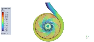
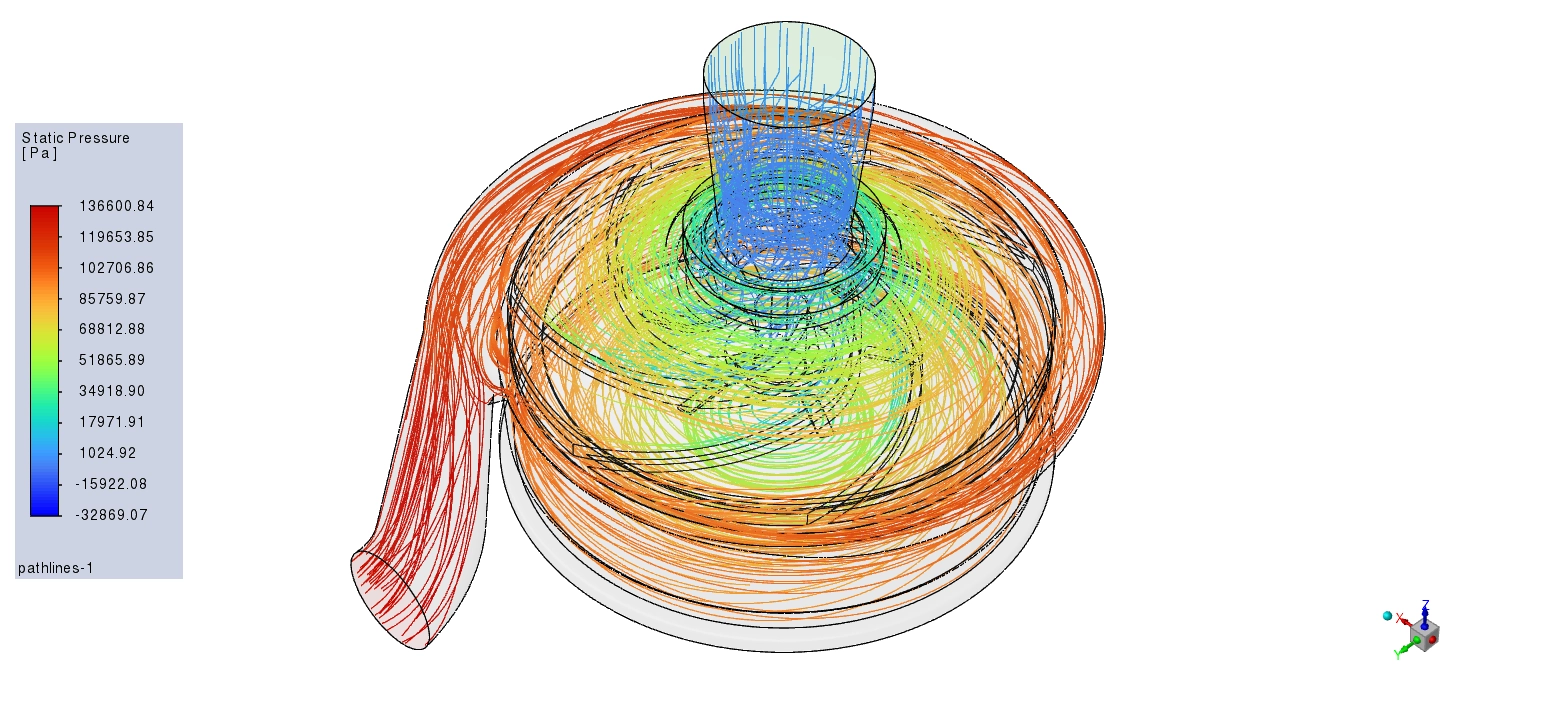
Figure 4: Velocity magnitude contours visualizing flow acceleration up to 15.49 m/s at the blade tips and deceleration inside the volute.
Frequently Asked Questions (FAQ)
- What does the MRF model do in a centrifugal pump CFD simulation?
- A:The Moving Reference Frame (MRF) model allows engineers to simulate rotating machinery without actually moving the mesh. It applies mathematical rotational forces (like centrifugal force) to the fluid inside the impeller zone, saving calculation time while maintaining high accuracy.
- Why is the pressure lowest at the center of the impeller?
- A: The center of the impeller, or the “eye,” is where the water enters. As the blades push water outward, it creates a slight vacuum or suction effect at the center. This low-pressure zone, measuring around 13,600 Pa, pulls new water into the pump continuously.
- How does the volute casing generate pump head?
- A:The volute is designed with an expanding spiral shape. When the fast 15.49 m/s water leaves the impeller and enters the wider volute, it slows down to 5 m/s. This physical deceleration converts the kinetic energy of the water into high static pressure, generating the 14.177 meters of head.


Reviews
There are no reviews yet.