


Cooling hot curved parts is a big problem in engineering. Devices like gas turbine blades and electronic chips often have curved shapes and get very hot. If they get too hot, they break. To fix this, engineers use a method called Impinging Jet cooling. This involves shooting a fast stream of air directly onto the curve. This method is much stronger than just letting air blow over the surface. To study this correctly, we use Impinging Jet on Concave Surface CFD simulation.
This project is an Impinging Jet on Concave Surface fluent tutorial. We will teach you how to set up and analyze this cooling process. We use ANSYS Fluent to see how the air hits the wall and removes the heat. By simulating this Impinging Jet on Concave Surface Simulation, we can find the best way to keep machines safe. For more lessons on thermal management, please visit our Heat Transfer tutorials. The geometry is based on the work of Hadipour et al. [1].
- Reference [1]: Hadipour, Amirhosein, and Mehran Rajabi Zargarabadi. “Heat transfer and flow characteristics of impinging jet on a concave surface at small nozzle to surface distances.” Applied Thermal Engineering138 (2018): 534-541.

Figure 1: The computational domain showing the nozzle inlet and the concave target surface.
Simulation Process: Structured Mesh and Ideal Gas Setup
To start this Impinging Jet on Concave Surface ANSYS fluent simulation, we created a 3D model. The model consists of a round nozzle (10-20 mm diameter) and a curved target wall (radius 50-100 mm). The mesh is the most critical part. We used a Structured Grid with exactly 39,468 cells. We used a “blocking technique” to arrange the cells neatly. We made the cells very small near the nozzle and the wall. This refinement is necessary to capture the thin layer of air that removes the heat.
In the ANSYS Fluent setup, we defined the air as an Ideal Gas. This is important because the density of air changes when it touches the hot wall. We set the nozzle inlet velocity to 6 m/s and the air temperature to 303 K. The curved wall was set as a heat source with a Constant Heat Flux of 2000 W/m². This setup mimics a hot engine part that needs to be cooled down rapidly.

Figure 2: Structured mesh with 39,468 cells showing refinement near the wall
Post-processing: Detailed Analysis of Jet Acceleration and Cooling
To understand the physics of this Impinging Jet on Concave Surface CFD simulation, we must follow the journey of the air. The story starts at the nozzle. The air shoots out at 6 m/s. It travels straight until it hits the concave wall. This impact zone is called the Stagnation Point. At this exact spot, the air is forced to turn 90 degrees. Because the wall is curved, the air gets squeezed and speeds up. The Velocity Contours in Figure 4 show this acceleration clearly. The red spots on the wall indicate that the air speed jumps to a maximum of 9.59 m/s. This fast-moving air forms a Wall Jet that scrubs the surface.
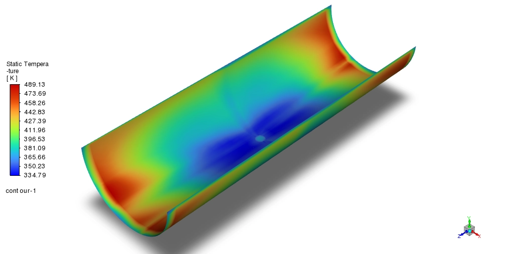
The second part of the story is about heat removal. We can see this in the Temperature Contours in Figure 3. The wall is generating heat at 2000 W/m². At the center, where the jet hits directly, the temperature is very low, ranging from 303 K to 335 K. This is because the fresh, cold air hits this spot first. However, as the air moves sideways along the curve, it picks up heat from the wall. By the time it reaches the edges, the air has become hot. The data shows the temperature at the outlet reaches 489 K. This is a massive increase of 186 K from the inlet. This tells engineers that the center is well-cooled, but the edges are much hotter.

Figure 3: Temperature contours showing the cold stagnation zone (303 K) and hot edges (489 K).

Figure 4: Velocity contours showing the jet acceleration to 9.59 m/s on the curved wall.
The final measure of success is the Nusselt Number (Nu). This number tells us how efficient the cooling is compared to just letting the air sit there. In natural cooling, the Nusselt number is usually small (between 5 and 20). In our Impinging Jet on Concave Surface fluent simulation, the calculated Nusselt number is 68. This is a huge improvement. It means this jet cooling method is roughly 3 to 10 times more effective than natural convection. This high efficiency proves that the acceleration of the air to 9.59 m/s along the curved wall is the key driver for keeping the component safe.
Key Takeaways & FAQ
- Q: Why use an Impinging Jet?
- A: It creates a high Nusselt number (Nu=68). This is much better than natural cooling for hot parts like turbine blades.
- Q: What happens to the air velocity?
- A: The air leaves the nozzle at 6 m/s but accelerates to 9.59 m/s when it hits the concave wall. This fast “Wall Jet” removes the heat.
- Q: Why is the Ideal Gas model used?
- A: In this Impinging Jet on Concave Surface fluent simulation, the temperature changes by 186 K. The Ideal Gas law allows the air density to change correctly with this heat.


Reviews
There are no reviews yet.