


Modern electronics, like 5G base stations and laser diodes, get incredibly hot. If they get too hot, they break. To fix this, engineers use a Large-scale Copper Microchannel Heat Sink. This device is a block of copper with thousands of tiny tunnels (microchannels) inside. Water flows through these tunnels to wash the heat away. However, simulating thousands of channels at once is too hard for computers. The solution is to use Large-scale Copper Microchannel Heat Sink CFD simulation with a special trick called “Periodic Boundary Conditions.”
This project is a Large-scale Copper Microchannel Heat Sink fluent simulation designed to teach you how to model just one single channel to understand the whole system. It is important to note that this is a CFD Simulation study, not a validation against experiments. We use ANSYS Fluent to predict the temperature and pressure. By simulating this Large-scale Copper Microchannel Heat Sink, we can optimize the cooling for high-power electronics. For more lessons on small-scale flows, please visit our Microfluids tutorials.
- Reference [1]: Sun, Bo, et al. “Pumping power and heating area dependence of thermal resistance for a large-scale microchannel heat sink under extremely high heat flux.” Heat and Mass Transfer2 (2022): 195-208.


Figure 1: Schematic of the microchannel unit cells.
Simulation Process: Periodic Boundary Setup in ANSYS Fluent
To start this Large-scale Copper Microchannel Heat Sink ANSYS Fluent tutorial, we created the geometry of a single unit cell. This represents just one channel out of the thousands in the real device. The mesh (grid) is very important for microchannels. We generated a very fine Structured Grid with 7,728,000 hexahedral cells. Hexagonal cells are shaped like bricks and give the most accurate results for flow inside square pipes. This high number of cells allows us to capture the behavior of water near the copper walls very precisely.
In the ANSYS Fluent setup, we applied “Periodic Boundary Conditions” to the side walls. This tells the software that this single channel repeats infinitely to the left and right. We set the fluid as Liquid Water and the solid as Copper (Thermal Conductivity 387.6 W/m·K). We applied an extremely high “Heat Flux” of 238.5 kW/m² to the bottom surface. This simulates the heat coming from a powerful computer chip. The water enters at 298.15 K (25°C). The solver calculates how the water moves and absorbs this massive energy.

Figure 2: The structured mesh grid with 7.7 million cells.
Post-processing: Analysis of Flow and Thermal Performance
To truly understand the performance of this Large-scale Copper Microchannel Heat Sink CFD simulation, we must look at the physics of the flow first. The velocity contours in Figure 4 show how the water moves through the channel. The color is red in the center and blue at the walls. This is a classic “Parabolic Profile.” The simulation data shows that the maximum velocity in the center reaches 3.31 m/s. This speed is critical. We calculated the Reynolds Number (Re) to be 778. In fluid dynamics, a Reynolds number below 2300 means the flow is “Laminar.” This means the water flows in smooth, straight layers without chaotic mixing. This is good because laminar flow requires less pumping power heat sink energy than turbulent flow, making the system more efficient.
The second part of the analysis focuses on the heat. The goal is to remove the massive 238.5 kW/m² heat load. The temperature contours in Figure 3 show the result. The water enters at 298.15 K. As it travels down the channel, it absorbs heat from the copper. The data shows the outlet temperature is 298.34 K. The rise in water temperature is only 0.19 K. This is a very small increase, which proves that the water is moving fast enough (3.31 m/s) to carry the heat away almost instantly. More importantly, we look at the solid copper temperature. The hottest point on the heat sink is 298.55 K. This is only 0.4 K hotter than the inlet water. This proves that the copper conducts the heat very well and the design prevents the chip from forming dangerous hot spots.
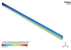
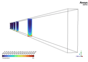
Figure 3: Temperature distribution showing the small 0.4 K rise.

Figure 4: Velocity pattern showing the laminar parabolic profile.
The final step is to calculate the efficiency using engineering metrics. The most important number for designers is the Thermal Resistance. Our result is 1.36×10⁻⁶ K/W. This number is extremely low. A low resistance means the heat flows easily from the chip to the water. This result confirms that the Large-scale Copper Microchannel Heat Sink is capable of cooling high-tech devices like 5G stations and Fusion Reactor walls without overheating.
Key Takeaways & FAQ
- Q: Why use Periodic Boundary Conditions?
- A: A real heat sink has thousands of channels. Simulating all of them is impossible. Periodic boundaries allow us to simulate just one channel in this Large-scale Copper Microchannel Heat Sink fluent simulation and get results for the whole device.
- Q: What does the Reynolds Number (Re=778) mean?
- A: It means the flow is Laminar. The water moves in smooth layers. This is important for calculating the correct pumping power heat sink requirements.
- Q: Is the cooling effective?
- A: Yes. The simulation shows a Thermal Resistance of only 1.36×10⁻⁶ K/W. The maximum temperature rise is less than 0.4 K, even with a high heat flux of 238.5 kW/m².


Reviews
There are no reviews yet.