


A Methanol Steam Reforming CFD simulation is a computer analysis that helps engineers design better chemical reactors for producing hydrogen. This process, where methanol and steam react to make hydrogen, is critical in the energy industry. A Steam Reforming Fluent Simulation allows us to see exactly how this reaction happens inside a reactor.
This report details a Wall reaction CFD study using ANSYS Fluent. In many industrial reactors, the chemical reaction happens on the surface of a catalyst on the reactor walls. To model this correctly, a custom program called a Steam reforming UDF (User-Defined Function) was used. This advanced approach allows the Species Transport model in Fluent to accurately predict reaction rates and product yield, leading to more efficient and optimized reactor designs. For more chemical engineering CFD tutorials, visit https://cfdland.com/product-category/engineering/cfd-in-chemical-engineering/.
- Reference [1]: Wang, Feng, Longjian Li, and Yanyun Liu. “Effects of flow and operation parameters on methanol steam reforming in tube reactor heated by simulated waste heat.” International Journal of Hydrogen Energy42 (2017): 26270-26276.
- Reference [2]: Purnama, Herry, et al. “CO formation/selectivity for steam reforming of methanol with a commercial CuO/ZnO/Al2O3 catalyst.” Applied Catalysis A: General1 (2004): 83-94.
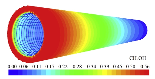
Figure 1: Schematic of the micro-tube reactor geometry used for the Methanol Steam Reforming CFD simulation, based on the reference study [1].
Simulation Process: Fluent Setup, Species Transport and UDF for Wall Reactions
The simulation process for this Steam Reforming CFD Simulation began with a 2D geometry of the reactor, designed based on a validated research paper [1]. A high-quality unstructured mesh was created with very fine inflation layers near the tube walls. This fine mesh is essential for an accurate Wall reaction Fluent simulation.
Inside ANSYS Fluent, the Species Transport model was activated to track the different chemical species involved, including methanol, steam, hydrogen, and carbon dioxide. Two key chemical reactions were defined. The primary reaction is Methanol Steam Reforming (MSR), and the secondary reaction is the Reverse Water-Gas Shift (RWGS). Because the speed (rate) of these reactions depends on temperature and species concentration in a very specific way, Fluent’s standard models could not be used. Instead, a custom UDF was written in the C programming language. This UDF programmed the exact rate expressions from the literature directly into the solver, ensuring the simulation’s chemical kinetics were highly accurate. The reactions were then applied as wall reactions, telling Fluent that the chemistry only occurs on the surface of the tubes.
Two main reactions are implemented using UDF in Ansys Fluent.
CH₃OH + H₂O → 3H₂ + CO₂, with rate expression rSR = kSR · exp(-Ea,SR/RT) · T · C⁰·⁶CH₃OH · C⁰·⁴H₂O.
CO₂ + H₂ → CO + H₂O, with rate expression rRWGS = kRWGS · exp(-Ea,RWGS/RT) · T² · CCO₂ · CH₂.
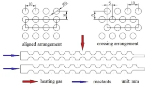
Figure 2: Schematic of micro-tube reactor and system design for waste heat recovery
Post-processing: Correlating Flow Dynamics with Reaction Performance
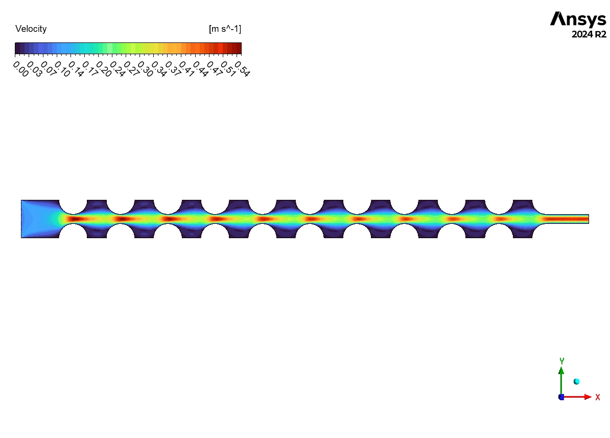
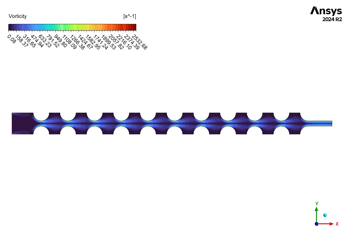
The simulation results provide a complete engineering analysis, successfully linking the reactor’s internal flow patterns directly to its chemical conversion efficiency. The engineering analysis begins with the fluid dynamics. The velocity streamlines in Figure 4 show that the flow is not simple. As the gas mixture flows past the circular tubes, it creates large recirculation zones (vortices) behind each one. This is a critical design feature. These vortices cause excellent mixing, constantly forcing the reactant chemicals (methanol and steam) from the main flow towards the tube walls. This enhanced mixing is the direct cause of the high reaction efficiency, as it ensures the reactants are continuously supplied to the catalytic surfaces where the reaction occurs.
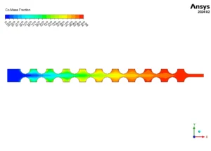
Figure 3: CO Mass Fraction distribution showing product formation along reactor length
Figure 4: Velocity field with streamlines from the Fluent simulation, showing the complex flow patterns and recirculation zones created by the tube arrangement.
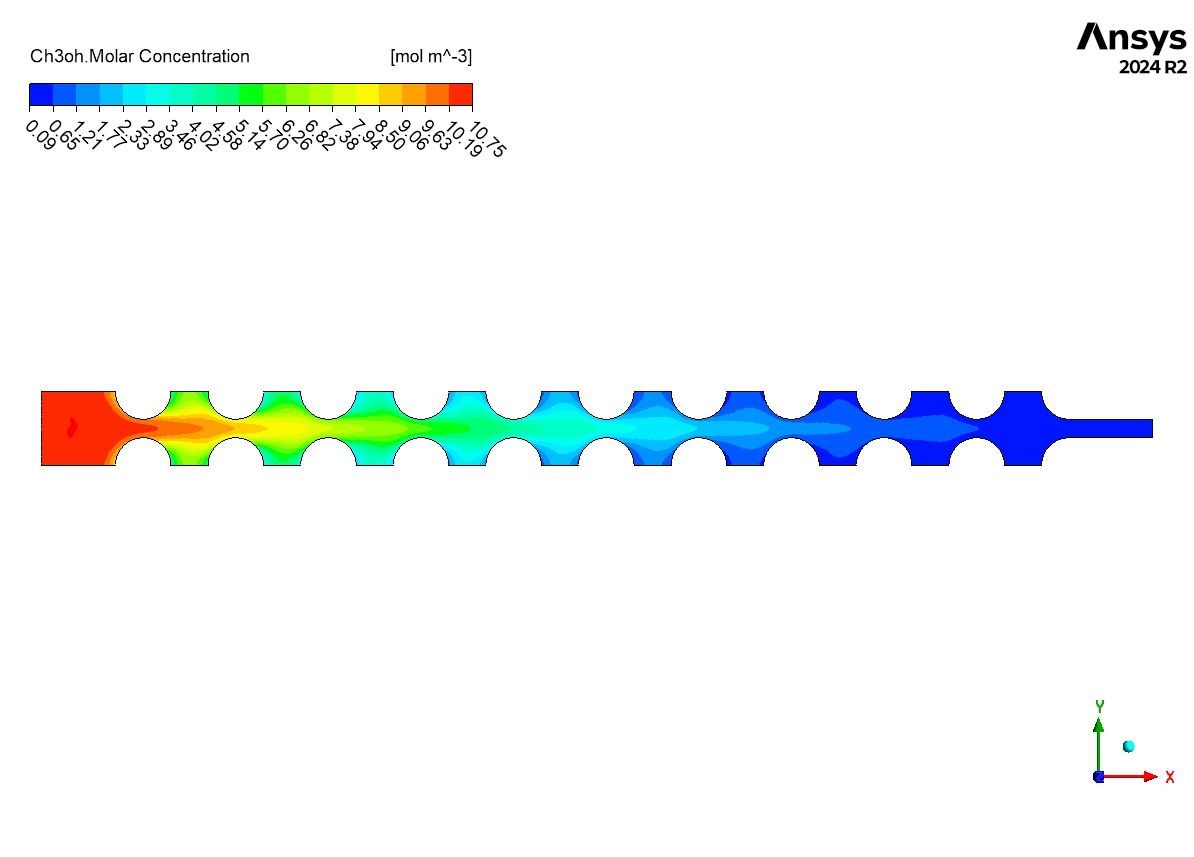
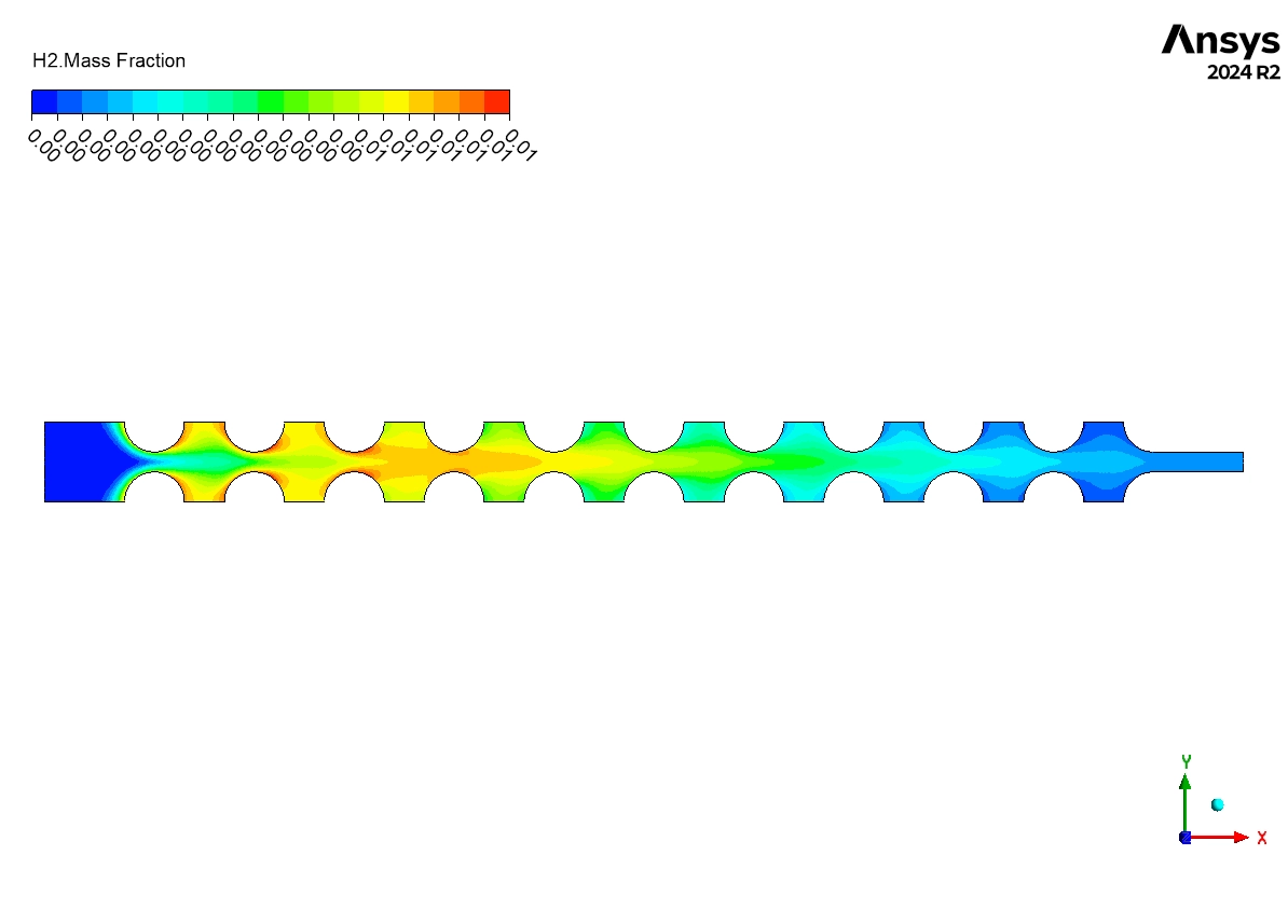
The species contours provide clear proof that this design is effective. The methanol concentration, shown in Figure 5, drops from 10.75 mol/m³ at the inlet to nearly zero at the outlet. This demonstrates almost complete consumption of the methanol fuel. As the methanol is consumed, the desired product, hydrogen, is created. Figure 6 shows the hydrogen mass fraction increasing steadily along the reactor, reaching its maximum value at the exit. This confirms a high yield of hydrogen. The formation of the CO byproduct, seen in Figure 3, also matches the expected chemical behavior.
The most important achievement of this simulation is the successful validation of the UDF-driven wall reaction model. The analysis proves that the geometrically-induced mixing is directly responsible for the excellent species conversion. By accurately predicting the complete consumption of methanol and the corresponding high yield of hydrogen, this Methanol Steam Reforming Fluent simulation serves as a powerful and reliable tool for designing and optimizing industrial-scale hydrogen production reactors.

Figure 5: Methanol molar concentration decrease from inlet to outlet
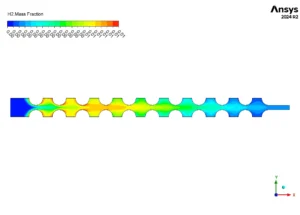
Figure 6: Hydrogen mass fraction increase confirming successful reforming


Reviews
There are no reviews yet.