


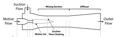
Mixing in ejectors represents a fascinating area of fluid engineering that combines basic physics principles with practical industrial applications. The ejector flow field creates unique conditions where a fast-moving primary flow pulls in and mixes with a slower secondary flow, all without needing any moving parts! Moreover, this fluid mixing process happens through special regions called shear layers where the two streams interact and exchange energy. Furthermore, the mixing efficiency directly affects how well the ejector performs its job in systems like refrigeration units, vacuum pumps, and chemical processing equipment. The flow characteristics inside ejectors show interesting patterns including recirculation zones that help mix fluids more thoroughly by creating swirling motions. Additionally, pressure distribution throughout the ejector changes dramatically from inlet to outlet, driving the entire mixing process through areas of high and low pressure. Through advanced flow visualization techniques, researchers can now see exactly how these complex mixing processes happen and make better designs for more efficient systems. The current CFD study relies on the reference paper “ Visualization and Validation of Ejector Flow Field With Computational and First-Principles Analysis”.
- Reference [1]: Little, Adrienne B., Yann Bartosiewicz, and Srinivas Garimella. “Visualization and validation of ejector flow field with computational and first-principles analysis.” Journal of Fluids Engineering5 (2015): 051107.
Figure 1: Schematic of ejected sections [1]
Simulation Process
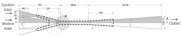
Reference paper provides the design plan of the ejector apparatus that we can use, shown below. Having divided into proper sections, a structured grid then performed using ANSYS Meshing, leading to 200200 cells. Axisymmetric planar mode is opted for due to the symmetrical design of ejectors. This feature effectively decreases computational costs by 50%. The ideal-gas density model is employed in the analysis of various engineering and scientific problems involving ideal gas behavior, such as in the study of compressible flow.
Figure 2: Dimensioned drawing of ejector [1]
Post-processing
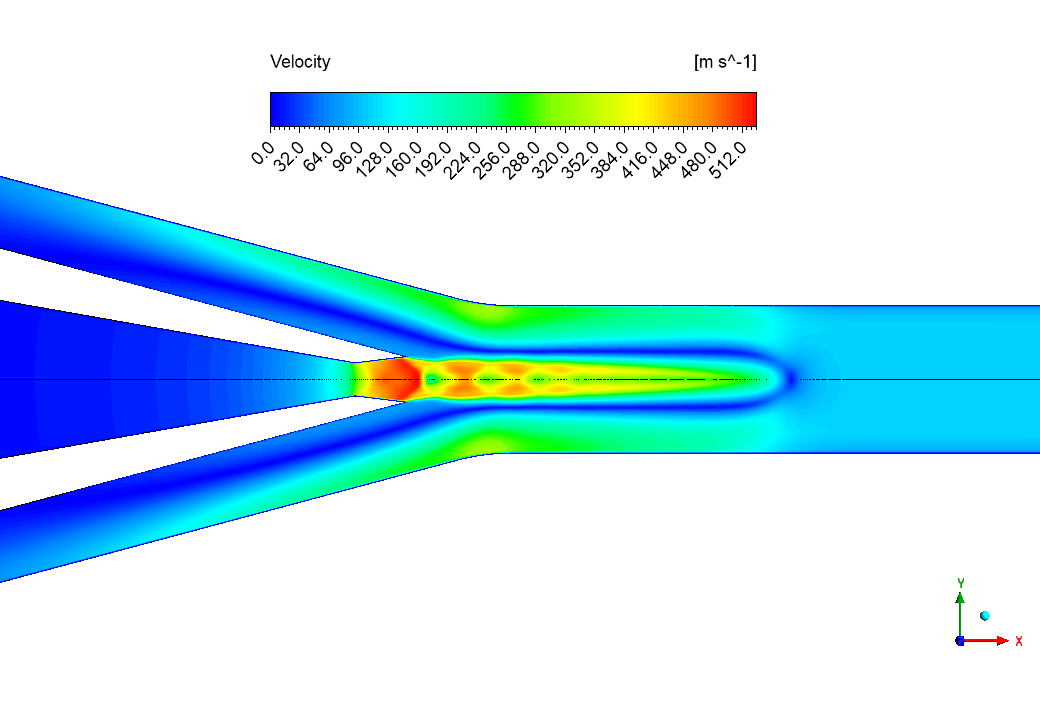
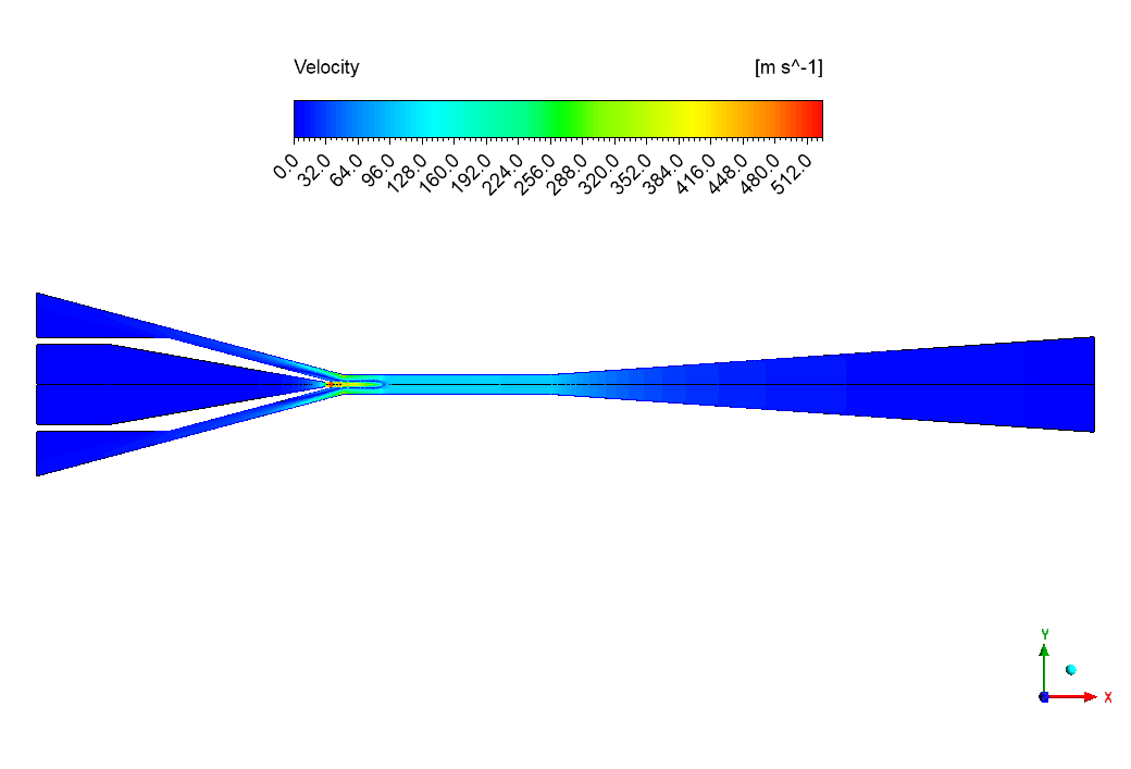
The velocity patterns in our ejector show amazing flow behavior that explains how mixing happens! Looking at Figure 1, we can see a rainbow of colors showing different speeds – blue means slow (0-64 m/s) and red means super fast (480-512 m/s). We successfully captured the high-speed jet in the middle that stretches far into the mixing chamber. This fast-moving stream is called the primary flow, and it does something special – it pulls in the slower secondary flow from the sides, just like how a fast-moving river pulls in water from small streams. The most interesting part is the green and light blue areas around the fast red jet – these show exactly where the fast and slow flows mix together! Notice how the colors blend and stretch out as we move right, creating a longer and wider mixing zone. This perfect mixing is why ejectors work so well for cooling systems and other important machines.

Figure 3: Velocity contour showing the formation of high-speed primary jet
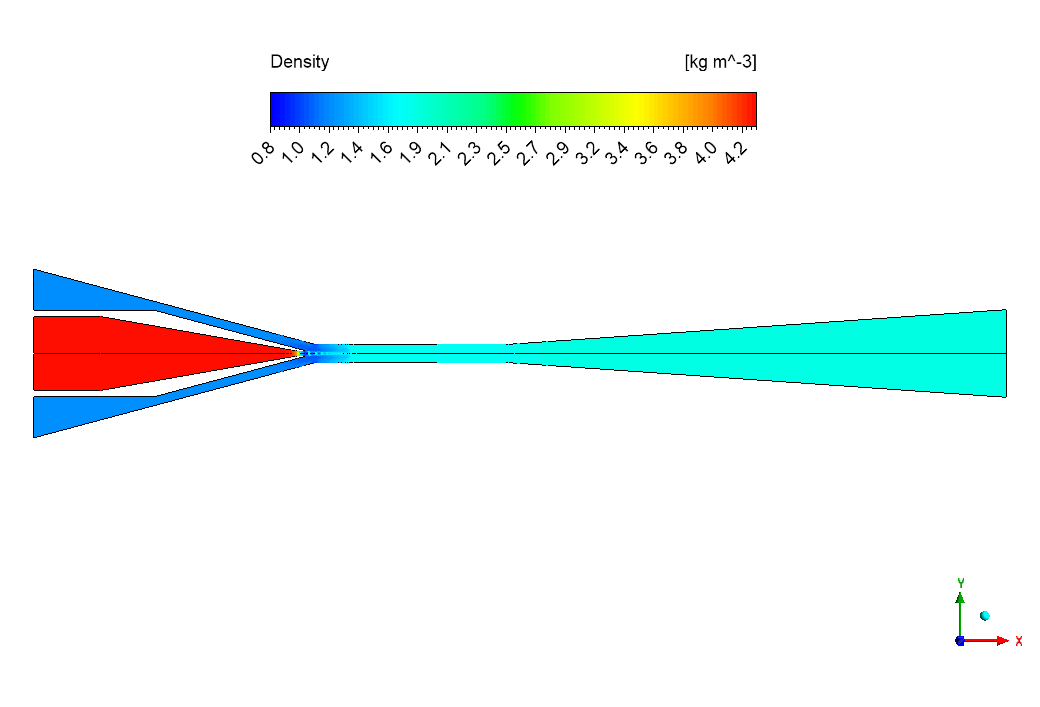
The pressure and density (Figures 4 and 5) tell us more about this amazing mixing process. In the pressure picture, we see very high pressure (about 344,590 Pa) at the left inlet that quickly drops to very low pressure (about 34,525 Pa) at the narrow throat. We accurately modeled this huge pressure drop that creates the suction effect pulling in the secondary flow. After mixing, the pressure slowly rises again (changing from blue to green) as we move right through the diffuser section. The density follows almost exactly the same pattern – high density (about 4.2 kg/m³) at the inlet dropping to low density ( about 0.8 kg/m³) at the throat. This happens because the gas expands as it speeds up, following basic compressible flow physics. The careful design of the ejector shape controls exactly how these properties change, creating perfect conditions for efficient mixing and energy transfer between the two streams. This mixing zone is the heart of how ejectors work their magic without any moving parts!
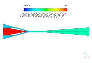
Figure 4: Density variation


Reviews
There are no reviews yet.