


Engines and computer chips get very hot. If we do not cool them, they break. Engineers use channels with “Ribs” to remove this heat. A rib is a small bump that disturbs the air. However, standard ribs create dead zones where hot air gets trapped. To fix this, we use a better design called Slit Ribs. These ribs have small cuts in them. To see how these cuts work, we use Slit Ribs In Channel CFD simulation.
This project is a Slit Ribs In Channel Fluent and ANSYS CFX tutorial. It is designed to teach you how to analyze airflow and heat. We use the software to visualize the high-speed air jets. By performing this Slit Ribs In Channel Simulation, we can predict how much heat is removed. For more examples of cooling systems, please visit our Heat Transfer tutorials. The geometry used here mimics the research by Zheng et al. [1].
- Reference [1]: Zheng, Daren, Xinjun Wang, and Qi Yuan. “The flow and heat transfer characteristics in a rectangular channel with convergent and divergent slit ribs.” International Journal of Heat and Mass Transfer141 (2019): 464-475.
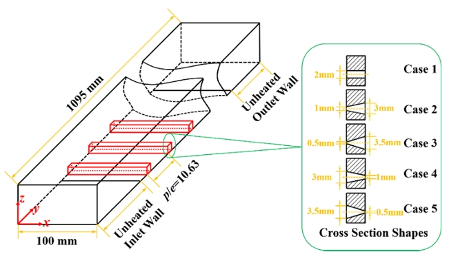
Figure 1: 3D Computational Domain showing the convergent slit ribs on the bottom wall. [1]
Simulation Process: Structured Meshing
For this Slit Ribs In Channel ANSYS Fluent type analysis, we created a 3D model of a rectangular channel with multiple slit ribs. The ribs are placed 50-100 mm apart. We generated a high-quality Structured Hexahedral Mesh using ANSYS ICEM CFD. We created a grid with 4,821,528 cells. We made the cells very small near the rib surfaces and the bottom wall. This is necessary to capture the “Viscous Sublayer” where the heat transfer happens.
We set up the physics using Air as an Ideal Gas. This means the air density changes when it gets hot. We set the Inlet Temperature to 298.15 K (25°C). We applied a Constant Heat Flux to the bottom wall to simulate the hot engine part. We used the SST k-omega Turbulence Model. This model is very good at predicting how air separates behind the ribs. We used Periodic Boundary Conditions to simulate a long channel by calculating only a short section. This makes the Slit Ribs In Channel simulation faster. The solver calculated the Navier-Stokes equations to find the velocity and temperature at every point.

Figure 2: Structured Mesh Generation in ICEM CFD, displaying the high-quality hexahedral grid with dense cell clustering near the rib surfaces and slit openings to capture boundary layers.
Post-processing: Thermo-Hydraulic Performance and Flow Physics Analysis
This section provides a deep engineering analysis of the CFD Analysis of Slit Ribs In Channel results. We interpret the contours and data to prove to manufacturers that slit ribs are better than solid ribs.
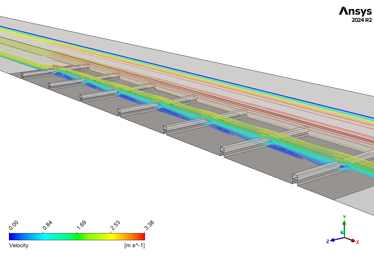
First, we analyze the Hydrodynamics (Velocity) shown in Figure 4.
- Jet Acceleration: The contours show that the air speeds up as it passes through the narrow slit. The velocity jumps from 2 m/s (Yellow) to a maximum of 3.28 m/s (Red).
- Secondary Jet Effect: This is the most important mechanical finding. This high-speed jet shoots through the rib and hits the area behind it. In a normal solid rib, this area is a “Dead Zone” where air stops moving. The Slit Jet washes this dead zone away. This active movement is critical for scrubbing heat off the wall.
Next, we evaluate the Thermal Performance using Figure 3 and the provided data.
- Temperature Rise: The air enters the channel at 298.15 K. As it moves over the hot ribs, it absorbs heat. The simulation calculates a precise Outlet Temperature of 304.229 K.
- Energy Balance: The increase from 298.15 K to 304.229 K proves that the air has successfully captured the thermal energy from the wall.
- Hot Spot Elimination: The contours show the wall temperature reaches a maximum of 511 K to 561 K (Red). However, looking closely at the area behind the slits, the color is Cyan/Blue (~350 K).
- Engineering Insight: This proves the slit jets are cooling the wall locally. The temperature gradient is broken by the turbulence.
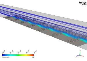

Figure 3: Temperature field with streamlines from slit ribs in channel CFD using ANSYS CFX

Figure 4: Velocity streamlines in ribbed channel CFD (blue 0 to red 3.28 m/s), mainstream flow 2-3
Key Takeaways & FAQ
- Q: Why are Slit Ribs better than solid ribs?
- A: Solid ribs create dead zones where heat gets trapped. Slit Ribs allow air to pass through, creating a Secondary Jet that cools the area behind the rib.
- Q: What is the maximum air velocity?
- A: The simulation shows the air accelerates through the slit to a maximum of 3.28 m/s.
- Q: How hot does the air get?
- A: In this Slit Ribs In Channel CFD simulation, the air enters at 298.15 K and heats up to 304.229 K at the outlet.


Reviews
There are no reviews yet.