
Industrial pipe systems often use flexible rubber rings to control fluid flow. When liquid or gas travels through an FSI tube, it pushes hard against the rubber surface. The rubber seal bends and deforms under this continuous pressure. But this bending changes the actual shape of the pipe path. The altered path then forces the fluid to move at a different speed. Understanding this continuous, chaotic feedback loop is physically impossible using a basic rigid model.
The objective of this project is to use ANSYS Fluent and the Structural module to predict the physical deformation of the rubber and calculate the resulting high-speed fluid velocity. By capturing this coupled interaction, engineers can verify if the internal stress stays within safe limits and ensure the seal will not tear under heavy airflow.
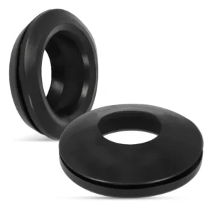
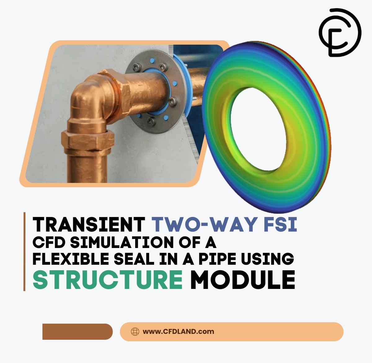
Figure 1: A physical photograph of typical flexible rubber seals used to control flow inside industrial pipe systems.
Simulation Process: Intrinsic FSI and Linear Elasticity Setup
We build a 3D computational model of a standard pipe containing a solid ring seal. The simulation starts by pushing air into the pipe inlet at a continuous velocity of 10 m/s. This represents a normal operating load for industrial ventilation or pneumatic systems. To solve this problem, we must configure two different mathematical solvers to communicate simultaneously. First, we use the ANSYS Structure module. We apply a linear elasticity solid model to the seal. This assumes the material follows Hooke’s law, meaning it will stretch and return to its original shape safely.
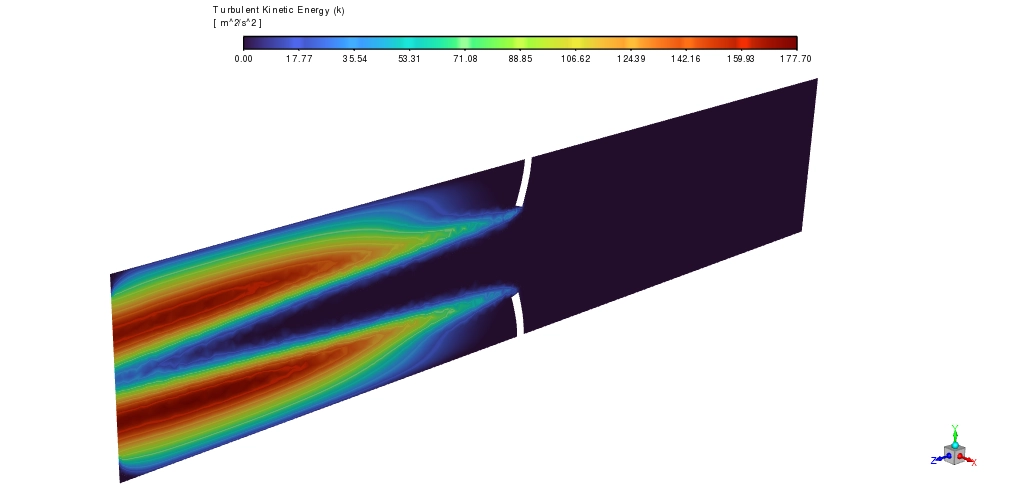
Then, we configure the fluid domain. As the solid rubber bends, the fluid space shrinks. The fluid mesh must instantly adapt. We activate the dynamic mesh smoothing method inside Fluent. This tool treats the fluid grid like an elastic web, stretching the boundary nodes smoothly without crashing the calculation. Fluent calculates the air pressure and sends it to the mechanical solver. The mechanical solver bends the rubber and sends the new shape back to Fluent. This continuous exchange of data creates an advanced fluid-structure interaction loop that mimics real-world physics flawlessly. In simple words, 2-way FSI model is setup.
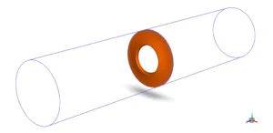
Figure 2: The geometric schematic defining the outer fluid pipe domain and the internal solid flexible seal.
Post-processing: Fluid Acceleration, Displacement, and von Mises Stress
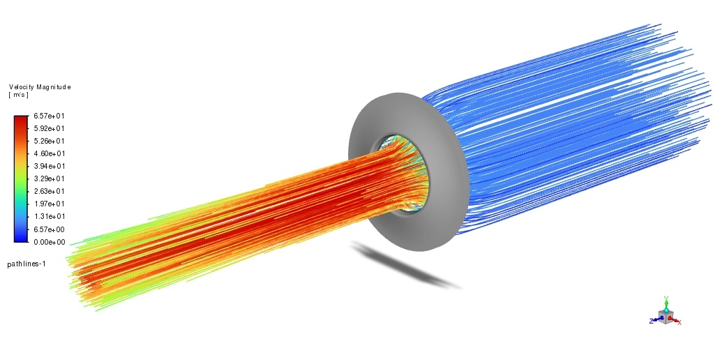
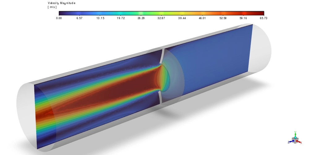
We thoroughly investigate the coupled physics by analyzing the velocity contours, the structural displacement map, and the internal stress generation. Firstly, we examine the fluid velocity. Air enters the wide pipe calmly at 10 m/s. As it approaches the seal, the solid rubber restricts the path. The fluid is forced to squeeze through a very narrow central gap. This sudden restriction forces the air to accelerate dramatically. The velocity contour hits a massive red maximum of 65.73 m/s right at the center of the gap. This extreme speed creates a strong low-pressure zone due to the Bernoulli effect. The incoming air pushes the front of the seal, while the fast air in the gap sucks the inner edge forward.
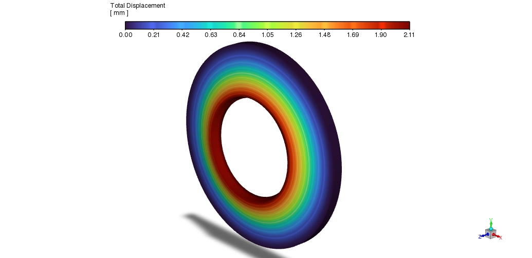
This combination of pushing and pulling forces creates an immediate structural reaction. We review the total displacement contour to measure this effect. The fluid pressure forces the rubber to bend sharply inward. The inner edge moves the most, reaching a maximum displacement of 2.11 mm at the tip. As we look closer to the outer pipe wall, the solid boundary holds the rubber firmly in place. The displacement drops smoothly to 0 mm at the outer edge.
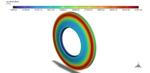
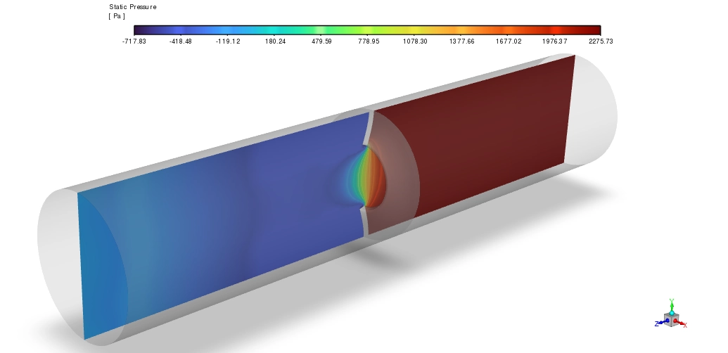
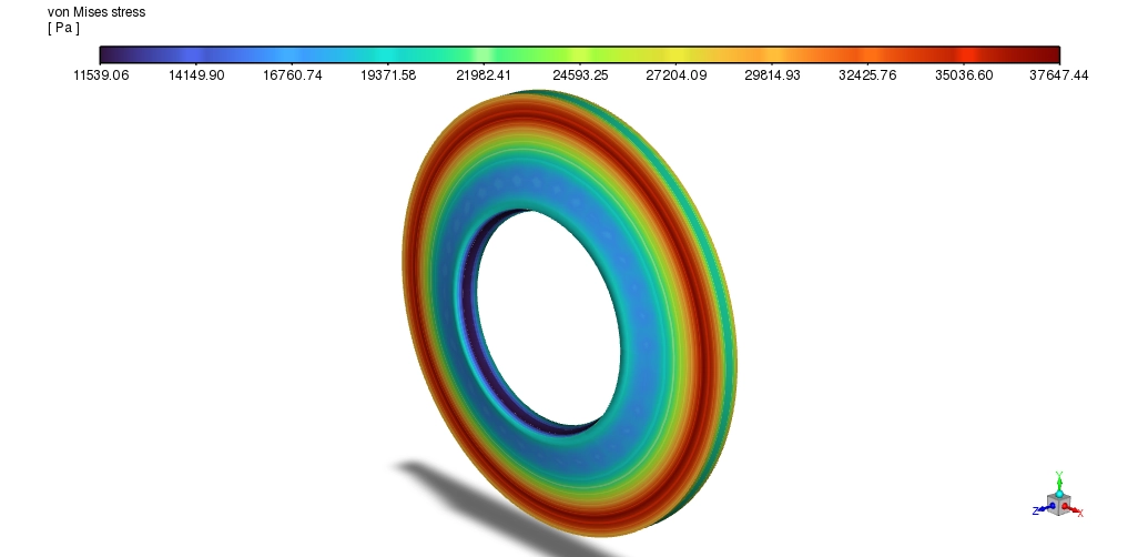
Figure 3: The von Mises stress distribution highlighting a maximum internal load of 37647 Pa at the sharpest bending corner.
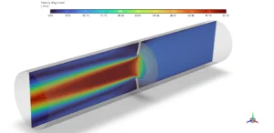
Figure 4: The velocity magnitude contour showing the fluid squeezing through the deformed seal and accelerating to a peak of 65.73 m/s.
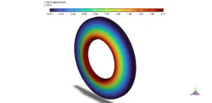
Figure 5: The total displacement map proving the fluid pressure bends the inner edge of the seal inward by 2.11 mm.
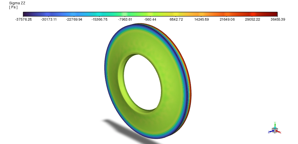
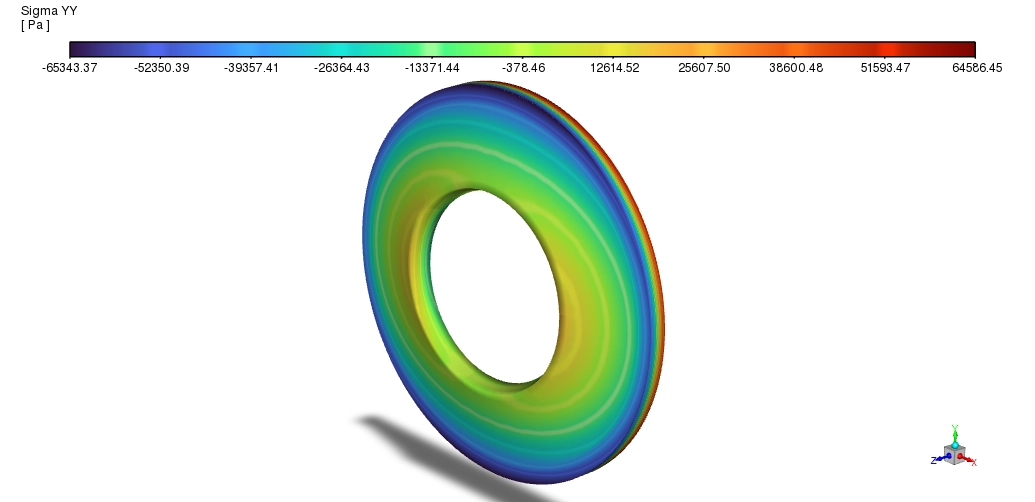
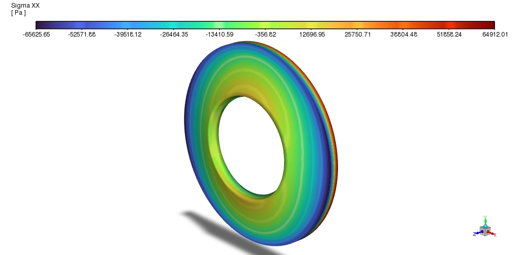
Finally, we should verify if this 2.11 mm bending will break the material. We evaluate the von Mises stress contour. The severe bending generates internal friction inside the rubber. The contour shows a bright red stress concentration directly at the inner corner where the bend is sharpest. The stress reaches a maximum peak of 37647 Pa. In engineering terms, this equals 0.038 MPa. This value is incredibly low. It remains perfectly within the safe operating limit for standard industrial polymers. This data completely captures the 2-way feedback loop. The structure bent by 2.11 mm, which forced the pipe gap to shrink, which then forced the fluid to spike to 65.73 m/s. The design is entirely safe and highly efficient.
FAQ About 2-Way FSI Tube CFD Modeling
- Why does the air velocity spike so dramatically inside the pipe?
- The rubber seal acts as a physical barrier. It forces the incoming 10 m/s airflow into a tiny central gap. Just like placing a thumb over a running water hose, this physical restriction forces the fluid to accelerate rapidly to 65.73 m/s.
- What does the Structure module do in this FSI simulation?
- The Structure module handles the solid mechanics. It receives the fluid pressure data from Fluent and calculates exactly how far the rubber material will bend, which in this case reaches a peak of 2.11 mm.
- Is the flexible seal in danger of breaking?
- No. The simulation proves that the maximum internal stress hits only 37647 Pa (0.038 MPa). This peak stress happens at the inner bending corner and stays well below the structural failure limit of standard industrial rubber.







Reviews
There are no reviews yet.