Vortex Shedding of Grooved Cylinder CFD Simulation, ANSYS Fluent Tutorial
Vortex Shedding of Grooved Cylinder CFD Simulation, ANSYS Fluent Tutorial
- Upon ordering this product, you will be provided with a geometry file, a mesh file, and an in-depth Training Video that offers a step-by-step training on the simulation process.
- For any more inquiries regarding the product, please do not hesitate to reach out to us at info@CFDLAND.com or through our online support assistant.
€140.00 Original price was: €140.00.€85.00Current price is: €85.00.
Title: Vortex Shedding of Grooved Cylinder CFD Simulation, ANSYS Fluent Tutorial
In fluid dynamics, vortex shedding in a grooved cylinder is an interesting effect to look at. The flow pattern is more complicated than it would be on a smooth cylinder because the surface has grooves. As fluid moves around the grooved cylinder, it breaks away from the surface at certain points. We left alterations of results for the post-processing section after CFD investigation. The grooves have a big effect on vortex generation process because they change how the boundary layer behaves, which could delay the separation of the flows, and they change the frequency and size of the shed vortices.
Simulation Process
Primarily, the smooth and grooved cylinder are designed using Design Modeler. They are placed in an extended computational zone. Needless to say, the grid production particularly around the cylinder walls is of the essence, directly affecting the accuracy. Consequently, a well-produced structured grid is created using ANSYS Meshing. Literally, the flow behavior is completely depend on flow regime. In our case of study, it is laminar. Focusing on vortices, the drag and lift coefficients are also measured.


Figure 1: Fine structured grid around grooved cylinder
Post-processing
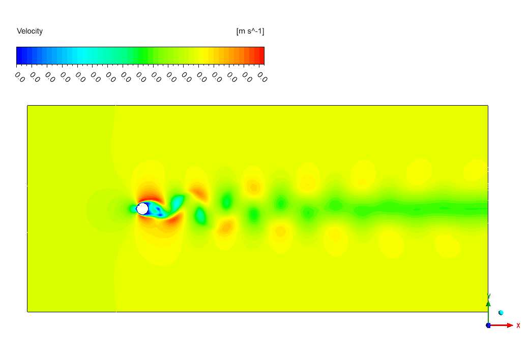
It’s interesting to see how fluid dynamics works when you simulate vortex shedding for a grooved cylinder in laminar flow. Behind the cylinder, the velocity streamline contour shows the well-known von Kármán vortex street pattern. The grooved shape, which can be seen as a small depression on the cylinder’s surface, seems to have a small effect on how the fluid flows. If we look at the difference between the drag coefficient (Cd) of a grooved cylinder (1.286) and a smooth cylinder (1.3), we see that the groove may be slightly better at keeping the flow from separating. The lift coefficient (CL), on the other hand, stays the same for both grooved and smooth cylinders at 0.0394, which shows that the groove doesn’t have a big effect on the lift forces. In the wake, the alternate vortices are easy to see, with areas of high speed (red and orange) and areas of lower speed (green and blue). The groove seems to slightly change the point where the flow separates, which could be one reason for the small drop in drag. general, the groove makes a small difference in reducing drag, but it doesn’t seem to have much of an impact on the general pattern of vortex shedding or lift forces.
We pride ourselves on presenting unique products at CFDLAND. We stand out for our scientific rigor and validity. Our products are not based on guesswork or theoretical assumptions like many others. Instead, most of our products are validated using experimental or numerical data from valued scientific journals. Even if direct validation isn’t possible, we build our models and assumptions on the latest research, typically using reference articles to approximate reality.
Yes, we’ll be here . If you have trouble loading files, having technical problems, or have any questions about how to use our products, our technical support team is here to help.
You can load geometry and mesh files, as well as case and data files, using any version of ANSYS Fluent.
€215.00 Original price was: €215.00.€165.00Current price is: €165.00.

€220.00 Original price was: €220.00.€115.00Current price is: €115.00.

€220.00 Original price was: €220.00.€115.00Current price is: €115.00.

€160.00 Original price was: €160.00.€135.00Current price is: €135.00.

€280.00 Original price was: €280.00.€145.00Current price is: €145.00.


Reviews
There are no reviews yet.