


This report shows how we used computational fluid dynamics (CFD) to study a wastewater sewage mixer using the Multi Reference Frame (MRF) method in ANSYS Fluent. Wastewater treatment is super important for keeping our environment clean and dealing with water contamination. Mixing equipment plays a big role in anaerobic tanks and aeration tanks that clean dirty water from cities and factories. The sewage mixer keeps the wastewater moving so sludge doesn’t build up on the bottom of the treatment tank. Our CFD simulation helps show how well the mixer propeller works without having to build and test expensive real-world equipment. Thanks to two reference papers “ MIXING PERFORMANCE OF SEWAGE TREATMENT MIXER AT DIFFERENT ROTATIONAL SPEED” and “ Numerical simulation and experimental investigation of submersible sewage mixer performance”, the present CFD study done by ANSYS fluent is conducted.
- Reference [1]: Tian, F., et al. “Mixing performance of sewage treatment mixer at different rotational speed.” ASME 2011 International Mechanical Engineering Congress and Exposition, IMECE 2011. 2011.
- Reference [2]: Błoński, D., et al. “Numerical simulation and experimental investigation of submersible sewage mixer performance.” Journal of Physics: Conference Series. Vol. 1741. No. 1. IOP Publishing, 2021.
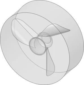
Figure 1: Schematic of mixer propeller zone
Simulation Process
The impeller and environment are initially designed using Spaceclaim. The sewage mixer propeller requires a circular zone around it to pave the way for using Multi Reference Frame (MRF) later. The complicated model then meshed inside Fluent meshing tool. The rotational velocity of 50rpm is applied. Notably, the angle of attack remains constant during the rotation, this is why let us utilize MRF approach.
Post-processing
The velocity distribution in Figure 1 shows how the wastewater mixer creates a powerful flow jet that extends into the tank. The highest velocity reaches 1.90 m/s near the propeller, but quickly drops to around 0.32-0.63 m/s (green-light blue region) as the flow moves deeper into the tank. This creates what engineers call a “jet flow pattern” that’s typical for axial flow mixers. The jet only reaches about 1/3 of the tank length with velocities above 0.32 m/s, which means we might need to increase the rotational speed or adjust the blade angle to get better mixing coverage in the far corners of the tank. The current setup might lead to “dead zones” in the tank corners where sludge could settle, reducing treatment efficiency. The flow pattern also shows slight asymmetry, suggesting possible turbulent instabilities that could actually help with mixing but might cause unwanted vibrations in the mixer shaft over time.
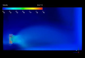
Figure 2: Velocity contour showing the flow field generated by the wastewater mixer
The pressure distribution on the propeller blades in Figure 2 reveals important details about the mixer performance. The leading edges of the blades show high pressure areas (red-orange, around 558-797 Pa) while the trailing edges show significant negative pressure (green-blue regions, -1114 to -636 Pa). This pressure difference is exactly what creates the thrust that pushes the water forward. The highest negative pressure (-3026 Pa) appears at the blade tips, which indicates potential for cavitation – tiny bubbles that could damage the blades over time if the mixer runs too fast. The pressure gradient is steepest near the blade tips, which matches theory since these areas move fastest through the water. The relatively even pressure distribution along each blade suggests good hydraulic efficiency, but the slightly higher pressures at the blade roots near the hub suggest we could improve the design by tweaking the blade twist to distribute the load more evenly. This would reduce energy consumption and extend the equipment lifespan by minimizing stress concentrations.
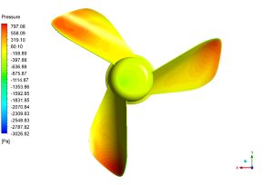
Figure 3: Pressure contour on the propeller blades showing the distribution


Reviews
There are no reviews yet.