
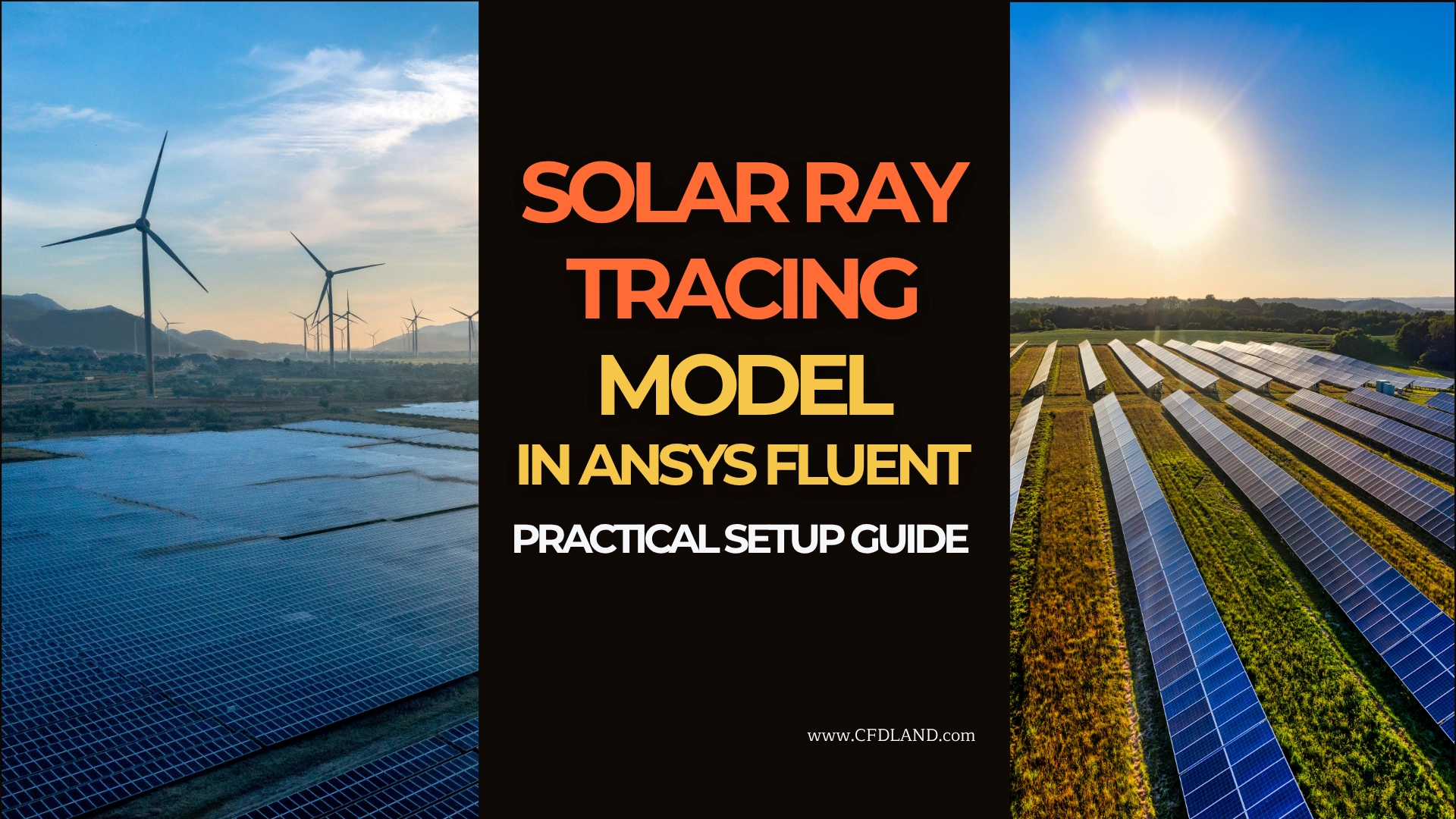
The Solar Ray Tracing Model in ANSYS Fluent is a useful tool for solar radiation CFD simulation. It helps engineers model heat from the sun. This heat can change wall temperature, air temperature, and flow behavior. It is important in many thermal CFD projects. Solar radiation can heat many surfaces. It can heat roofs, walls, glass windows, solar collectors, PV panels, and outdoor devices. In a CFD model, this heat is called solar load. ANSYS Fluent can calculate this load with the Solar Load Model in ANSYS Fluent. In case you are interested in step-by-step CFD tutorials regarding radiation and solar load modeling in ANSYS Fluent, please check our radiation library. You`ll definitely find the catch.
Figure 1: Example of Solar Ray Tracking Model Simulation in ANSYS Fluent Software
The main idea is simple. The sun sends rays to the model. Fluent follows these rays. Then Fluent calculates the solar heat flux in Fluent on each surface. A sunny wall gets more heat. A shaded wall gets less heat. This helps users study shadow simulation in Fluent and surface heating.
The ANSYS Fluent Solar Ray Tracing model is very useful when sun direction is important. For example, it can be used in building solar load CFD simulation. It can also be used in solar collector CFD simulation, greenhouse CFD simulation, car cabin solar radiation simulation, and HVAC solar load simulation. This article is a practical guide. It explains the main inputs, such as sun position in ANSYS Fluent, direct solar radiation, diffuse solar radiation, and the solar calculator in Fluent. It also explains the main setup steps, boundary conditions, and result checks. Radiation heat transfer has many models in ANSYS Fluent. If you need a full guide about them, read this article: Complete Guide to ANSYS Fluent Radiation Models for CFD Simulations. In this article, we focus only on solar ray tracing CFD and solar load setup.
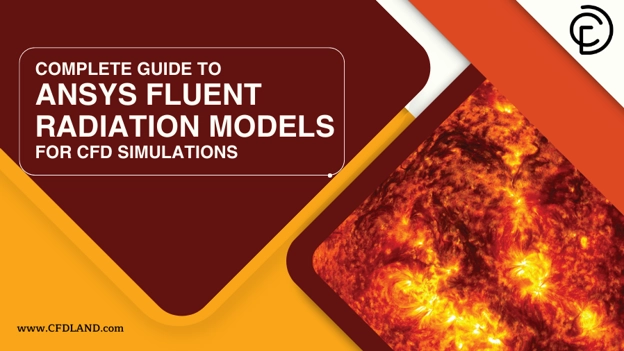
Figure 2: CFDLAND article- Complete Guide to ANSYS Fluent Radiation Models for CFD Simulations.
This topic is not a full review of all ANSYS Fluent radiation models. Here, we study solar heat only. We focus on solar irradiation input, wall heating, wall absorptivity, glass transmissivity, and solar radiation boundary condition. These items are very important for correct solar results. CFDLAND also offers practical ANSYS Fluent heat transfer tutorials and thermal CFD simulation products. These products help users learn real Fluent setup, radiation heat transfer in Fluent, solar load simulation, and post-processing. The Solar Ray Tracing Model in ANSYS Fluent helps users calculate solar heat flux, solar heat gain, and shadow effects in real CFD models.
What Is Solar Ray Tracing and Where Is It Used?
Solar ray tracing is a method for solar heat transfer. It follows the path of sunlight in a CFD model. In ANSYS Fluent Solar Ray Tracing, the sun is a heat source. The rays come from one direction. This direction depends on the sun position, time, date, and project location. In a real case, sunlight can hit a wall, a roof, a glass window, or a solar panel. Part of this energy can be absorbed. Part of it can be reflected. If the surface is transparent, part of it can pass through the surface. This is very important in solar radiation CFD simulation. In Solar Ray Tracing Model in ANSYS Fluent, Fluent follows the solar ray path. Then it finds where the rays hit the surfaces. After that, Fluent adds solar energy to those surfaces as heat. This heat can increase wall temperature. It can also increase air temperature near the wall.
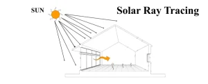
Figure 3: Solar Ray Tracing CFD simulation. Solar rays enter the domain and heat walls, glass, and solid surfaces.
The model can also show shadow. If a part blocks sunlight, the surface behind it receives less solar energy. This is called shadow simulation in Fluent. It is useful for buildings, solar collectors, cars, and outdoor devices. For example, a building wall can be hot on the sunny side. The shaded side can stay cooler. A glass window can pass sunlight into a room. This creates solar heat gain inside the room. In a solar collector, the absorber plate receives strong incident solar radiation. Then the plate temperature increases. Solar Ray Tracing is useful when sun direction, shadow, and solar heat flux are important in the CFD model.
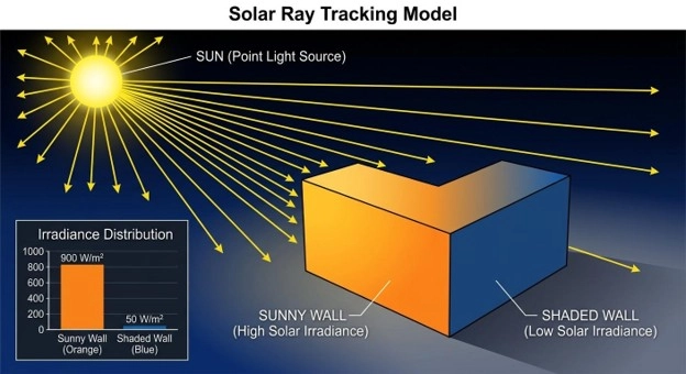
Figure 4: Shadow simulation in Fluent. The sunny wall receives high solar heat flux, but the shaded wall receives lower solar heat.
CFDLAND has several practical tutorials in this field. These tutorials help users learn ANSYS Fluent heat transfer, solar load setup, Solar Ray Tracing, ventilation, drying, greenhouse flow, and solar thermal systems. The table below gives a simple guide to the related CFDLAND products.
| Application Category | CFDLAND Product | Main Use | Product Link |
| Room ventilation and solar heat gain | Solar Heat Effect in Room Ventilation CFD Simulation | Study solar heat effect on indoor airflow and temperature. | View Tutorial |
| Building thermal comfort | Thermal Comfort CFD Simulation in Atrium Building with Solar Radiation | Study solar radiation, indoor comfort, and building airflow. | View Tutorial |
| Natural ventilation | Solar Chimney CFD Simulation Using Solar Ray Tracing Model | Study buoyancy flow, solar heating, and chimney ventilation. | View Tutorial |
| Greenhouse ventilation | Greenhouse Ventilation Considering Relative Humidity CFD Simulation | Study airflow, temperature, and humidity in a greenhouse. | View Tutorial |
| Solar distillation | 3D Solar Still Distiller Transient CFD Simulation | Study transient solar heating, evaporation, and distillation. | View Tutorial |
| Solar drying | Indirect Solar Dryer CFD and DPM Simulation | Study hot airflow, drying, and particle tracking with DPM. | View Tutorial |
| Passive solar building | Trombe Wall CFD Analysis with Solar Load and Fan Boundary | Study solar wall heating, thermal storage, and room airflow. | View Tutorial |
| Solar collector | Flat Plate Solar Collector CFD Simulation Using Solar Ray Tracing Model | Study solar heat flux, absorber temperature, and fluid heating. | View Tutorial |
These tutorials are useful for users who want to learn real solar CFD simulation training in ANSYS Fluent. They show how solar radiation can affect airflow, heat transfer, wall temperature, glass heat gain, and system performance.
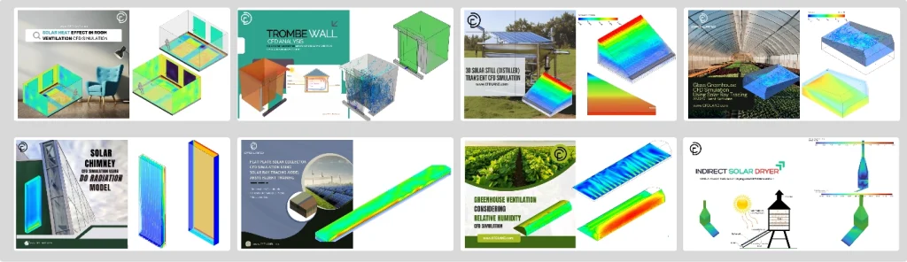
Figure 5: CFDLAND Solar Ray Tracing tutorials for ANSYS Fluent. These products cover solar heat transfer, ventilation, greenhouse flow, solar collectors, and solar drying.
The Solar Load Model in ANSYS Fluent is very useful for design work. Engineers can use it before they build a real system. They can test different designs. They can check hot zones. They can also reduce solar heat problems. For a building, this model can help find the best window size. It can also help study roof heating. For a car cabin, it can help find the effect of glass on cabin temperature. For a solar collector, it can help improve the absorber plate design. This model is also useful with thermal CFD simulation. Solar heat can create natural convection. Warm air rises. Cold air moves down. This flow can change comfort, cooling demand, and device temperature.
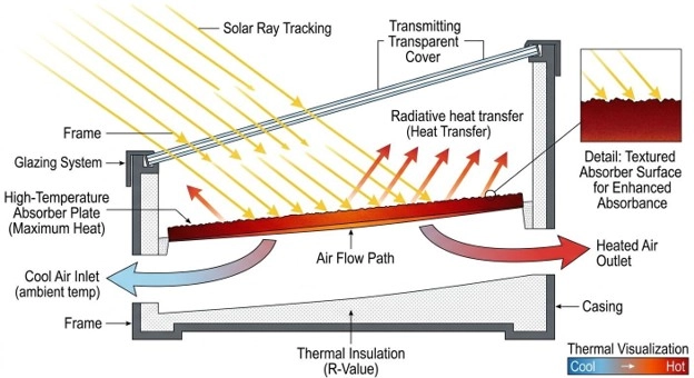
Figure 5: Solar collector CFD simulation. Solar rays heat the absorber plate and increase the air temperature inside the channel.
In CFDLAND projects and training products, many heat transfer cases use the same idea. Solar heat, wall heat flux, temperature contour, and airflow must be checked together. These real cases help users learn ANSYS Fluent heat transfer tutorials and solar CFD simulation training in a practical way. The main point is simple. Solar ray tracing does not only add heat. It adds heat based on sun direction and surface position. So the geometry, glass, wall type, and shadow must be correct. This makes the result closer to the real solar system.
Solar Inputs, Variables, and Fluent Settings
Before the Solar Ray Tracing setup in Fluent, the user must know the main solar energy terms. When solar radiation reaches a surface, it can have three paths. A part can be absorbed. A part can be reflected. If the surface is transparent, a part can be transmitted.
This balance can be written as a simple heat transfer equation:

Here, GG is the total incident solar radiation on the surface. Gabs is the absorbed solar radiation. Gref is the reflected solar radiation. Gtr is the transmitted solar radiation.
The same relation can be written with three coefficients:

In this equation:
| Symbol | Name | Simple Meaning |
 |
Absorptivity | Part of solar energy absorbed by the surface |
 |
Reflectivity | Part of solar energy reflected by the surface |
 |
Transmissivity | Part of solar energy passed through the surface |
So, for a surface:


For an opaque wall, solar radiation cannot pass through the wall. So:

Then the equation becomes:

For a glass window, γ\gamma is not zero. This means part of the solar energy can pass through the glass. This is very important in solar heat gain, transparent wall solar radiation, and building solar load CFD simulation. Correct values of absorptivity, reflectivity, and transmissivity are very important for Solar Ray Tracing Model in ANSYS Fluent.
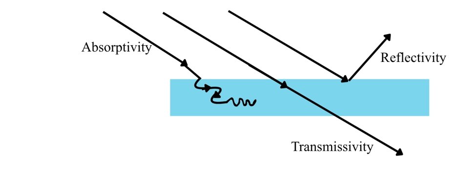
Figure 6: Solar radiation balance on a surface. Part of the incident solar radiation is absorbed, part is reflected, and part is transmitted through a transparent surface.
Solar Load Model Setup in Ansys Fluent
Before using the Solar Ray Tracing Model in ANSYS Fluent, the heat transfer model must be active. Solar load adds heat to the model. So, Fluent must solve the energy equation. Solar Load in ANSYS Fluent works only in the 3D solver, and it can be used for steady and transient simulations.
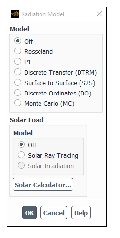
Figure 7: Radiation Model dialog box in ANSYS Fluent. The Solar Load Model is activated from this window.
In the Radiation Model dialog box, Fluent gives two main solar load options:
Table 1: Solar Ray Tracing and Solar Irradiation option
| Solar Load Option | Main Use | Important Point |
| Solar Ray Tracing | Calculates solar heat flux and adds it as a heat source in the energy equation. | It can work alone or with a radiation model. |
| Solar Irradiation | Sends solar beam and irradiation data to the DO or MC radiation model. | It is available only when DO or MC radiation model is active. |
For most engineering cases in this article, Solar Ray Tracing is the main option. It traces the sun rays. It checks shadows. It calculates solar heat flux in Fluent on walls, glass, inlets, outlets, and porous jumps.
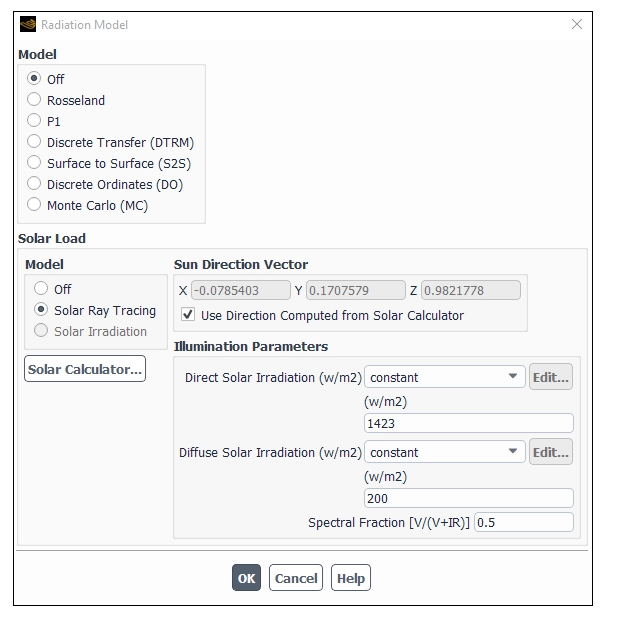
Figure 8: Solar Ray Tracing option in the Radiation Model dialog box. This option calculates solar heat flux and shadow in ANSYS Fluent.
The second option is Solar Irradiation. To use it, first turn on the Discrete Ordinates (DO) model or the Monte Carlo (MC) model. Then select: Solar Irradiation
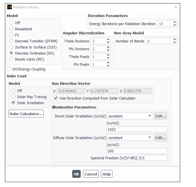
Figure 9: Solar Irradiation option in ANSYS Fluent. This option sends solar beam data to the DO or MC radiation model.
The difference is simple. Solar Ray Tracing calculates the solar load itself and applies it as heat sources. Solar Irradiation does not calculate wall heat flux directly. It gives solar beam direction and intensity to the DO or MC model. Then the radiation model solves the radiation heat transfer.
Table 2: difference Solar Ray Tracing and Solar Irradiation
| Item | Solar Ray Tracing | Solar Irradiation |
| Needs DO or MC? | No | Yes |
| Calculates solar heat flux? | Yes | No, DO or MC solves it |
| Adds heat source to energy equation? | Yes | No direct solar source from ray tracing |
| Good for shadows? | Yes | Depends on DO or MC setup |
| Main use | Fast solar load and shadow | Solar radiation inside a participating radiation model |
After selecting the solar load option, define the Sun Direction Vector. This vector points from the model to the sun. You can enter the X, Y, and Z values by hand. You can also let Fluent calculate it with the Solar Calculator. For Solar Ray Tracing, also define the illumination data:
Table 3: Solar Ray Tracing illumination data
| Input | Meaning |
| Direct Solar Irradiation | Direct sun beam energy in W/m2W/m^2. |
| Diffuse Solar Irradiation | Sky radiation energy in W/m2W/m^2. |
| Spectral Fraction | Fraction of direct solar radiation in the visible band. |
| Time Steps Per Solar Load Update | Update rate for transient solar load cases. |
The Spectral Fraction is used in Solar Ray Tracing. It divides the direct solar radiation into visible and infrared parts.

Here, V is visible solar radiation. IR is infrared solar radiation.
Now open the Solar Calculator.
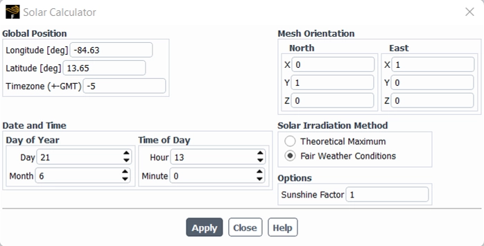
Figure 10: Solar Calculator dialog box in ANSYS Fluent. This window calculates sun direction and solar irradiation from location, time, and mesh orientation.
Solar Calculator: Global Position Inputs
The Solar Calculator dialog box in ANSYS Fluent is used to define the position of the project on the earth. Fluent uses this data to calculate the sun direction vector and the solar irradiation. The Global Position part includes Longitude, Latitude, and Time Zone.
| Input | Description |
| Longitude (deg) | This is the east-west position of the project location. The value is entered in degrees. It can range from -180 to +180. Negative values show the Western Hemisphere. Positive values show the Eastern Hemisphere. |
| Latitude (deg) | This is the north-south position of the project location. The value is entered in degrees. It can range from -90 to +90. Positive values show the Northern Hemisphere. Negative values show the Southern Hemisphere. |
| Time Zone | This is the local time zone relative to GMT. The value is entered in hours. It can range from -12 to +12. |
In the ANSYS Fluent Solar Calculator, latitude and longitude define the real place of the project on Earth. Fluent uses this location with date and time to calculate the sun direction vector and solar irradiation. Latitude shows the north or south position from the Equator. The Equator is 0°. North latitude is positive. South latitude is negative. Longitude shows the east or west position from the Prime Meridian. The Prime Meridian is 0°. East longitude is positive. West longitude is negative.
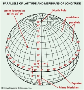
Figure 11: Parallels of Latitude and Meridians of longitude
For example, the point 40°N, 30°W means:
- 40°N: the point is 40 degrees north of the Equator.
- 30°W: the point is 30 degrees west of the Prime Meridian.
- In Fluent, this is usually entered as:
- Latitude = 40
- Longitude = -30
Correct latitude and longitude are important because they control the calculated sun position in ANSYS Fluent. This example point is in the North Atlantic Ocean. It is used here only to show how latitude and longitude are read. The Solar Calculator needs five groups of data.
Table 4: The Solar Calculator Input.
| Solar Calculator Input | Description |
| Longitude | East or west position of the project. Negative values show the western hemisphere. |
| Latitude | North or south position of the project. |
| Time Zone | Local time zone relative to GMT. |
| Date and Time | Day, month, hour, and minute of the simulation. |
| Mesh Orientation | North and East vectors in the CFD mesh. |
| Solar Irradiation Method | Method for solar data calculation. |
| Sunshine Fraction | Reduction factor for cloud effect. Default is 1. |
The mesh orientation is very important. The North and East vectors must match the real direction of the geometry. If these vectors are wrong, the sun will hit the wrong wall. Then the shadow simulation in Fluent will be wrong. The Solar Calculator has two solar irradiation methods:
Table 5: two solar irradiation methods
| Solar Calculator Method | Meaning | When to Use |
| Fair Weather Conditions | Uses ASHRAE fair weather data. It includes more atmosphere loss. | Best for normal clear-day engineering cases. |
| Theoretical Maximum | Uses a maximum solar intensity method from NREL data. | Best for upper-limit or ideal solar studies. |
The Fair Weather Conditions method is the default method. It is usually more realistic than the theoretical maximum method. The Theoretical Maximum method gives higher solar values. In real life, these values may not occur because the atmosphere reduces solar energy. After setting the Solar Calculator, click Apply. Fluent reports the output in the console. The output includes:
Table 6: Solar Calculator output
| Solar Calculator Output | Meaning |
| Sun Direction Vector | Direction from the model to the sun. |
| Sunshine Fraction | Applied reduction factor. |
| Direct Normal Solar Irradiation | Direct solar beam at the earth surface. |
| Diffuse Solar Irradiation | Sky radiation for vertical and horizontal surfaces. |
| Ground Reflected Irradiation | Diffuse radiation reflected from the ground. |
For transient simulations, set Time Steps Per Solar Load Update. This tells Fluent how often it must update the sun position and solar load. A small value gives more correct moving shadows. A large value reduces cost but may miss sun movement.
One important point is needed for Solar Irradiation with DO or MC. The beam direction for DO or MC has the opposite sign of the solar load sun direction vector. The solar load vector points to the sun. The DO or MC beam direction shows radiation coming from the sun. A correct solar load setup starts with Energy On, correct solar model choice, correct Solar Calculator data, and correct mesh orientation.
Boundary Conditions for Solar Ray Tracing
After the solar inputs are set, the next step is the solar radiation boundary condition setup in ANSYS Fluent. This step is very important. The Solar Ray Tracing Model in ANSYS Fluent uses boundary zones to know where solar rays enter, stop, pass, or lose energy. In ANSYS Fluent, solar boundary settings are set from Boundary condition panel. Open each boundary and go to the Radiation tab.
As we know all outer sides of the model should be included for ray tracing. This is important for correct shadow simulation in Fluent. If a wall or internal zone is excluded from the solar load calculation, Fluent treats it like a transparent surface. In simple words, solar rays can pass through it with no effect. In Solar Ray Tracing, a boundary must participate in the solar calculation, or Fluent will ignore it for solar ray interaction.
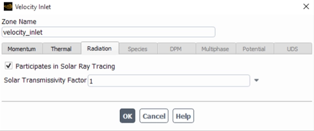
Figure 12: Velocity Inlet Radiation tab in ANSYS Fluent. The option “Participates in Solar Ray Tracing” lets inlet and outlet boundaries interact with solar rays.
For inlet and outlet zones, the user can enable Participates in Solar Ray Tracing. This option is enabled by default. If it is turned off, the surface is ignored. The solar ray will pass through this boundary with no interaction. For flow boundaries, ANSYS Fluent also gives a Solar Transmissivity Factor. This value controls how much solar irradiation enters the domain. A value of 1 means full solar transmission. A lower value reduces the solar energy. For example, a value of 0.5 cuts the incoming solar source by half. This factor is applied to both direct solar radiation and diffuse solar radiation.
Table 7: main boundary types for ANSYS Fluent Solar Ray Tracing.
| Boundary Type | Main Solar Setting | Physical Meaning |
| Velocity inlet / outlet | Participates in Solar Ray Tracing | Solar rays can enter or leave through this zone. |
| Opaque wall | Absorptivity | The wall absorbs and reflects solar energy. |
| Semi-transparent wall | Absorptivity and transmissivity | The wall can absorb, reflect, and pass solar energy. |
| Glass wall | Glass transmissivity | Solar energy can pass through the glass. |
| Porous jump | Absorptivity and transmissivity | It can model a grate, grid, blind, or louver. |
| Excluded wall | Not participating | Fluent treats it like a transparent surface. |
For wall boundaries, the user must choose the wall type in the Radiation tab. The wall can be opaque or semi-transparent. An opaque wall in ANSYS Fluent does not pass solar radiation. It absorbs part of the incident solar radiation. It reflects the rest. For an opaque wall, the user enters Direct Visible absorptivity and Direct IR absorptivity. These values define how much radiation the wall absorbs in the visible and infrared bands.
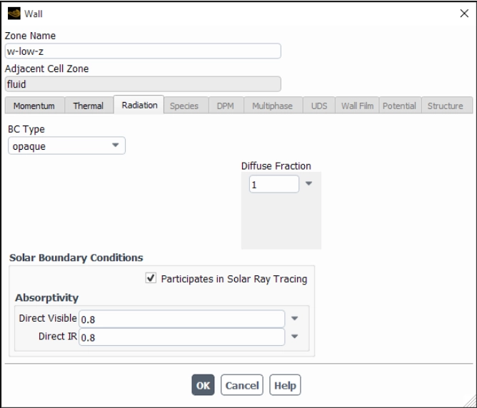
Figure 13: Opaque wall solar settings in ANSYS Fluent. The wall absorbs solar radiation in visible and infrared bands and does not transmit rays.
A semi-transparent wall in ANSYS Fluent can pass part of the solar radiation. This is important for glass, plastic covers, greenhouse walls, and glazed facades. For this wall type, the user enters absorptivity and transmissivity values. These values are used for direct visible, direct infrared, and diffuse hemispherical radiation. This setup is very important for transparent wall solar radiation and solar gains through glass. If the glass transmissivity is too high, too much heat enters the space. If it is too low, the indoor solar heat gain becomes too small.
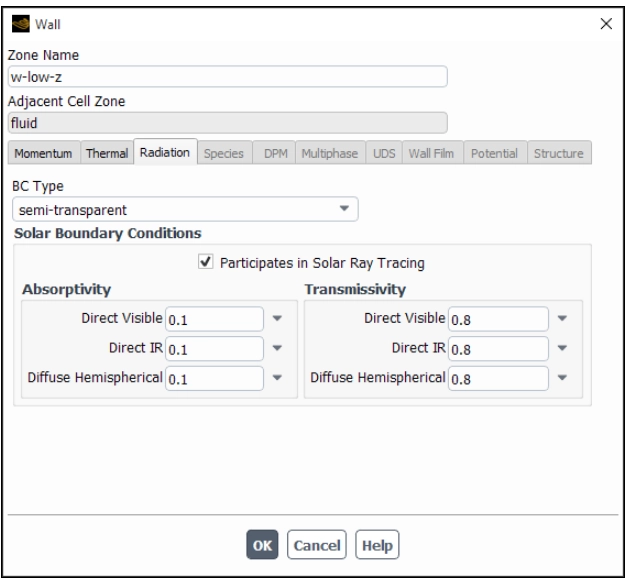
Figure 16: Semi-transparent wall solar settings in ANSYS Fluent. Glass and transparent walls need absorptivity and transmissivity for solar load simulation.
For semi-transparent coupled walls, ANSYS Fluent help notes that the solar ray tracing settings must be defined on the original wall, not on the shadow wall. This is a useful point in conjugate heat transfer cases.
Radiant Properties for Opaque and Transparent Surfaces
In ANSYS Fluent Solar Ray Tracing, each surface must have correct radiant properties. These properties control how much solar energy is absorbed, reflected, or transmitted.
For opaque materials, the user must know the absorptivity for two bands:
- Visible band or short-wave radiation
- Infrared band or long-wave radiation
Usually, absorptivity is higher in the infrared band. This is important for walls, floors, steel frames, and furniture.
- For opaque surfaces, absorptivity is the main input because solar radiation cannot pass through the material.
- For transparent surfaces, such as glass, the user must define both absorptivity and transmissivity. These values must be given for visible and infrared parts of direct radiation.
The value is entered for normal incident radiation. Fluent then corrects it for the real angle of solar ray impact. This is important because sunlight usually does not hit glass at exactly 90 degrees. For transparent surfaces, Fluent uses the normal-incidence data and automatically adjusts it for the actual angle of incidence.
For diffuse radiation, the user must also define overall absorptivity and transmissivity. This value is a hemispherical average value. It is mainly important for infrared diffuse radiation.
The values in the table below are taken from ASHRAE reference data. ASHRAE means the American Society of Heating, Refrigerating and Air-Conditioning Engineers. It is a global engineering group. It publishes trusted standards and design data for buildings, HVAC systems, heat transfer, ventilation, and energy use.
ASHRAE data helps engineers choose correct input values for building and thermal simulations. In this article, the table gives typical radiant properties of common surfaces. These properties include absorptivity and transmissivity for walls, floors, furniture, steel frames, and glass. This table is useful for ANSYS Fluent Solar Ray Tracing because surface properties control how much solar energy is absorbed, reflected, or transmitted.
Table 8: Typical radiant properties for common surfaces in Solar Ray Tracing setup
| Surface | Material | Radiant Properties |
| Walls | Matt white paint |  |
| Flooring | Dark grey carpet |  |
| Furnishings | Various, generally mid-colored matt |  |
| Steel frame | Dark grey gloss |  |
| External glass | Double glazed coated glass |  |
| Internal glass | Single layer clear float glass |
|

Where:
| Symbol | Meaning |
 |
Absorptivity for visible solar radiation |
 |
Absorptivity for infrared radiation |
 |
Diffuse absorptivity |
 |
Transmissivity for visible solar radiation |
 |
Transmissivity for infrared radiation |
 |
Diffuse transmissivity |
These values can be used as first estimates when exact manufacturer data are not available. But for final engineering design, real material data should be used.
Fluent calculates reflectivity from absorptivity and transmissivity. The relation is:
Reflectivity = 1 – (Absorptivity + Transmissivity)
So, the user must choose valid values. The sum of absorptivity and transmissivity should not be more than 1.
Table 9: General Reflectivity Guide Table
| Surface Type | Absorptivity | Transmissivity | Reflectivity |
| Opaque dark wall | High | 0 | Low to medium |
| Opaque light wall | Low | 0 | High |
| Clear glass | Low to medium | High | Low to medium |
| Tinted glass | Medium | Medium | Medium |
| Louver or blind | Depends on solid part | Depends on open area | Calculated by Fluent |
A porous jump can also participate in solar ray tracing CFD. This is useful for grates, grids, porous blinds, and louvers. A porous jump can pass fluid flow and also pass part of the solar radiation. This makes it useful in building solar load CFD simulation, HVAC solar load simulation, and car cabin solar radiation simulation.
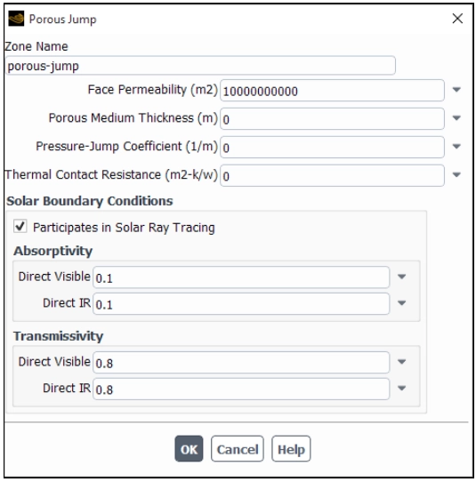
Figure 17: Porous Jump solar settings in ANSYS Fluent. This boundary can model blinds, louvers, and grids that pass part of the solar radiation.
For a porous jump, the user can set Direct Visible absorptivity, Direct IR absorptivity, Direct Visible transmissivity, and Direct IR transmissivity. ANSYS Fluent help gives a simple idea for grids. If 40% of a grid area is blocked, and the slats have absorptivity 0.7, the estimated absorptivity is:

For transmissivity, the open area fraction can be used as a simple estimate. For example, if a grid has 60% open area, the solar transmissivity can be close to 0.6.
The main rule is simple. If a surface blocks light in the real model, it must participate in the solar load calculation. If it does not participate, the solar ray path will pass through it. Then the solar heat flux in Fluent, wall heat flux, and temperature contour can be wrong. Correct boundary conditions control absorption, reflection, transmission, and shadow in Solar Ray Tracing in ANSYS Fluent.
Geometry and Mesh Notes for Solar Ray Tracing
Geometry and mesh have a direct effect on ANSYS Fluent Solar Ray Tracing. The solar rays move through the CFD domain and hit faces. So the model shape must be correct.
The Solar Ray Tracing Model in ANSYS Fluent uses a shading algorithm. Fluent checks if one face blocks the sun ray before it reaches another face. This is how shadow simulation in Fluent is created. For a correct solar radiation CFD simulation, all real walls, windows, inlets, outlets, and obstacles must exist in the geometry. If a wall blocks sunlight in the real system, it must also block sunlight in the CFD model. If it is removed or excluded, Fluent can treat that path like a transparent path. Then the solar heat flux in Fluent can be wrong.
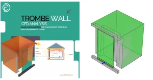
Figure 18: Simple building or room geometry with sun rays, windows, walls, and one internal obstacle creating a shadow.
Trombe Wall CFD Analysis: Solar Load and Fan Boundary Condition Simulation in ANSYS Fluent is a great example of designing and modeling using solar ray tracking settings. The mesh does not need a special radiation mesh. But surface faces must describe the geometry well. Very rough surfaces can give poor shadow borders. Very fine meshes can increase solar load calculation time.
Table 9: Geometry or Mesh Item To improve mesh quality
| Geometry or Mesh Item | Why It Matters |
| External enclosure | It controls where solar rays enter or leave. |
| Glass surfaces | They control solar gains through glass. |
| Internal obstacles | They create shadow zones. |
| Wall face direction | It affects incident solar radiation. |
| Surface mesh quality | It helps create cleaner solar heat flux contours. |
| Very large mesh | It may increase solar calculation time. |
ANSYS Fluent help also notes one limit. Non-conformal interfaces are not supported for Solar Ray Tracing. So the geometry and mesh connection must be planned with care. Also, Solar Ray Tracing includes only boundary zones next to fluid zones in the ray tracing calculation. Boundaries attached only to solid zones are treated as transparent in the ray tracing algorithm. This is important in conjugate heat transfer cases. For very large meshes, Fluent uses a quad-tree refinement factor for the shading algorithm. The default value is 7. It can be changed from the text interface if needed.
Define => Models => Radiation => Solar => Parameters => Quad => Tree => Refinement
In short, keep the geometry real, keep the surface mesh clean, and check all blocking parts. This helps Fluent calculate better solar heat flux contour, wall heat flux, and temperature contour.
Practical Solar CFD Applications and CFDLAND Tutorials
The Solar Ray Tracing Model in ANSYS Fluent is useful in many real systems. It can show where solar energy enters, where heat is absorbed, and where shadow forms. So, it is very useful for solar heat transfer CFD simulation, building solar load CFD, greenhouse CFD simulation, and solar collector CFD simulation.
The main value of Solar Ray Tracing in Fluent is that it connects sun position, solar heat flux, wall temperature, and airflow in one CFD model.
In post-processing, the user should first check the solar heat flux contour. This contour shows where the sun rays hit the model. Then the user should check the temperature contour, wall heat flux, airflow path, and shadow zone.
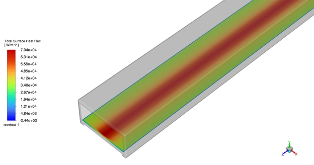
Figure 19: Solar heat flux contour in ANSYS Fluent. This result shows where solar energy reaches the surface and where shadow forms.
The Solar Ray Tracing Model in ANSYS Fluent is used in many solar and thermal systems. It can show solar heat flux, wall heating, glass heat gain, shadow, airflow, and temperature change. Solar CFD simulation is useful when sunlight changes the heat transfer and airflow inside or around a system.
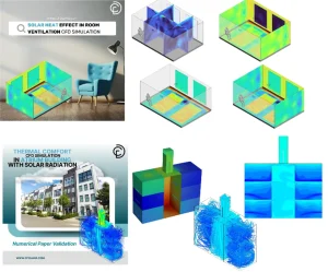
Figure 20: Two important and practical CFDLAND Tutorials for using Solar Ray Tracing settings.
Conclusion
The Solar Ray Tracing Model in ANSYS Fluent is a useful tool for solar heat transfer studies. It helps the user model sun rays, solar heat flux, shadow, wall heating, and solar gain through glass.
In this article, we reviewed the main parts of a correct solar load setup. These parts include solar inputs, the Fluent Solar Calculator, boundary conditions, wall absorptivity, glass transmissivity, geometry notes, post-processing, and common errors.
The most important point is simple. The result is only valid when the sun direction, solar data, and boundary conditions are correct. So, the user must always check the solar heat flux contour first. This contour shows if the sun rays and shadows are in the right place.
The ANSYS Fluent Solar Ray Tracing method can be used in many systems, such as solar chimneys, greenhouses, solar collectors, Trombe walls, solar dryers, solar stills, and room ventilation. With good setup and careful result checks, it can help engineers design better solar and thermal systems.
For more practice, users can study ANSYS Fluent heat transfer tutorials and solar CFD simulation training from CFDLAND. These tutorials help connect theory, Fluent settings, and real CFD results in one workflow.