

Mostly in civil engineering, the OCF full form stands for Open Channel Flow. This is the movement of a liquid, like water, with a free surface. A free surface is the top of the liquid that touches the air. Think of a river, a dam spillway, or waves in the ocean. Unlike flow in a closed pipe which is driven by pressure, open channel flow is driven by gravity. Understanding these flows is highly useful for many engineering fields. It helps us design safe dams, build strong offshore structures, and manage water resources effectively. Since these flows involve many changing variables, we rely on Computational Fluid Dynamics. A CFD simulation in ANSYS Fluent lets us see how water will move and what forces it will create before anything is built.
Before we start, here are several practical examples of open channel flow modeling projects performed by CFDLAND: Flow over a Cylindrical Weir, Water behavior in a Stepped Converging Spillway, accurate flow measurement with a Sharp-crested Weir, The impact of waves on an Offshore Column using FSI, The movement of a Tsunami Wave Generation, and General simulation of Free-surface Waves.
These advanced simulations usually rely on tracking the free surface between water and air. You can find detailed tutorials for these applications and many more in our multiphase CFD simulation library.


Figure 1: Examples of open channel flow simulations, from weir and spillway analysis to large-scale wave modeling
Understanding Open Channel Flows: Theory and Physics
An open channel flow is when a liquid, like water, flows with a free surface. This means the top of the liquid is open to the air. The pressure on this surface is uniform atmospheric pressure. The main force that makes the liquid move is gravity. Think of natural rivers or artificial canals used for irrigation. This is very different from pipe flow, where water is pushed by a pressure difference and there is no free surface.
The free surface is the main feature of open channel flow. It is the boundary between the liquid and the air above it. The behavior of this surface, especially how waves form and move, sits at the heart of free surface modeling in open channel hydraulics. Every free surface CFD setup starts by describing this boundary correctly. When setting up a CFD wave theory model, we categorize free-surface waves based on water depth. In deep-water waves, water particles move in circles. In shallow-water waves, their movement is more elliptical. The change from deep to shallow happens when the water depth is less than half the wave’s length.
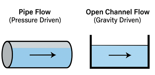
Figure 2: The key difference between pipe flow and open channel flow. Open channel flow has a free surface and is driven by gravity.
To understand the behavior of these flows, engineers rely on a fundamental dimensionless number. This is called the Froude Number (Fr). The Froude Number helps us classify the flow. It compares the speed of the water to the speed of a wave on the surface. The equation for the Froude Number is:
Fr = V / √(gh)
Here, V is the water velocity, g is gravity, and h is the water depth. You can think of it simply as Fr = (Water Velocity) / (Wave Velocity). You can also use our free non-dimensional numbers calculator to easily calculate the Froude number (Fr) for your conditions.
Based on the Froude Number, we can classify open channel flow into three types:
- Subcritical Flow (Fr < 1): This is a slow, calm flow. The water velocity is less than the wave velocity. In this case, waves can travel upstream. This means that a change downstream (like a gate closing) can affect the flow upstream.
- Critical Flow (Fr = 1): The water velocity is exactly equal to the wave velocity. This is a special transition point where the flow behavior changes.
- Supercritical Flow (Fr > 1): This is a fast, rapid flow. The water velocity is greater than the wave velocity. In this case, waves cannot travel upstream. This means that downstream changes do not affect the flow upstream.
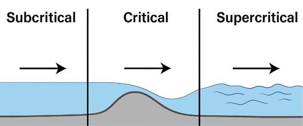
Figure 3: Flow classification based on the Froude Number. The flow changes from subcritical to supercritical as it passes over an obstacle
Types of Waves and Choosing the Right Wave Theory
Waves on the free surface are not all the same. Some are simple and smooth, while others are steep and turbulent. In ANSYS Fluent, you need to select the correct mathematical model, called a wave theory, to describe the waves in your simulation. Choosing the wrong one will give incorrect results.
Waves can be regular, with a constant height and period, or irregular, where each wave is different. For regular waves, we have several theories:
- First-Order Airy Wave Theory (Linear): This is for simple, small-amplitude waves. The wave shape is a perfect, smooth sine curve. This theory works well for waves in deep to intermediate water depths that are not very steep.

Figure 4: A linear wave described by Airy Wave Theory. It has a simple, symmetrical shape and is used for small-amplitude waves
- Higher-Order Stokes Wave Theory (Non-linear): When waves become steeper or move into shallower water, their shape changes. The crests get sharper and the troughs get flatter. For these steeper waves, we need a non-linear theory like Stokes Wave Theory.

Figure 5: A non-linear wave described by Stokes Theory. The crest is sharper and higher than the trough, which is a more realistic shape for steep waves
- Cnoidal / Solitary Wave Theory (Non-linear): For waves in very shallow water, the shape changes even more. They have long, flat troughs and narrow crests. We use Cnoidal Theory for these waves. A Solitary wave is a special type of cnoidal wave with an infinitely long wavelength. it looks like a single hump of water traveling.
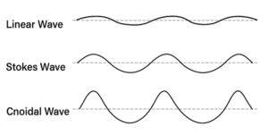
Figure 6: simple diagram showing linear, non-linear and cnoidal wave
How to Choose: The Ursell Number
So, how do you know which theory to use? The decision depends on the water depth, wave height, and wavelength. Engineers use the Ursell Number (U) to help make the right choice. The equation for the Ursell Number is:
U = \frac{H g^2}{T^2}
Here, H is the wave height, L is the wavelength, and h is the water depth.
- If the Ursell Number is small, a linear theory like Airy is often good enough.
- If the Ursell Number is large, you have to use a non-linear theory like Stokes or Cnoidal.
In ANSYS Fluent, you can perform a “Wave Input Analysis” that checks these numbers for you and recommends the best CFD wave theory for your specific problem. This is a very helpful tool to make sure your simulation setup is physically correct.
Open Channel Flows in ANSYS Fluent
To model a free surface in ANSYS Fluent, we need a method that can track the boundary, or interface, between two fluids that do not mix, like water and air. The most common method for this is the Volume of Fluid (VOF) model. A cell with a water volume fraction of 1 is full of water. A cell with a volume fraction of 0 is full of air. Cells with a value between 0 and 1 contain the free surface.
The first step in any open channel flow simulation is to activate the correct physical models.
- Go to Setup -> Models -> Multiphase -> Edit…
- In the Multiphase Model dialog box, select Volume of Fluid (VOF).
- Define your phases. Typically, air is the primary phase and water is the secondary phase.
- Furthermore, under VOF Sub-Models, you have to enable open channel flow simulation. This tells fluent you are modeling a gravity-driven flow with a free surface.
For wave simulations, you should also enable Open Channel Wave BC. This will unlock the advanced wave generation options at the boundaries.
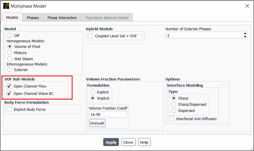
Figure 7: Activating the necessary models for an open channel flow simulation. The VOF model is selected, and the Open Channel Flow and Wave BC sub-models are enabled
Boundary Conditions for Open channel flow
After setting up the VOF model, the next step involves defining your inlets and outlets. Proper open channel flow boundary conditions in CFD tell the software how the fluid enters and leaves your simulation domain. For open-channel flow modeling, these settings are different from standard pipe flow because we have to define the position of the free surface.
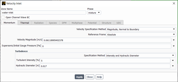
Figure 8: Defining the inlet and outlet boundary conditions is essential for a correct open channel flow simulation
The upstream boundary is where the water enters your model. Here, you need to specify how much water is coming in and where the free surface is located. The two most common options are:
- Pressure Inlet: You define the height of the water at the inlet. Fluent uses this height to calculate the hydrostatic pressure profile. This is useful when you know the water level but not the flow rate.
- Mass-Flow Inlet / Velocity Inlet: You define the mass flow rate or velocity of the water entering the domain. This is better when you know exactly how much water is flowing, for example, from a pump or a known river flow rate.
Fluent uses these two values to correctly calculate which part of the inlet boundary is water and which part is air.
The downstream boundary is where the water leaves your model. The most common choice is the Pressure Outlet. This condition is very flexible, especially for subcritical flows (Fr < 1) where downstream conditions can affect the upstream flow. When setting up a Pressure Outlet, you again need to specify the Free Surface Level. This tells Fluent the expected water height at the outlet. For supercritical flows (Fr > 1), the flow is not affected by downstream conditions, so the software will calculate the outlet properties from the cells just inside the domain.
Advanced: Open Channel Wave Boundary Conditions
If you are simulating waves, you need to use a special boundary condition. After enabling the Open Channel Wave BC option in the model panel, you can set up a Velocity Inlet to generate waves.
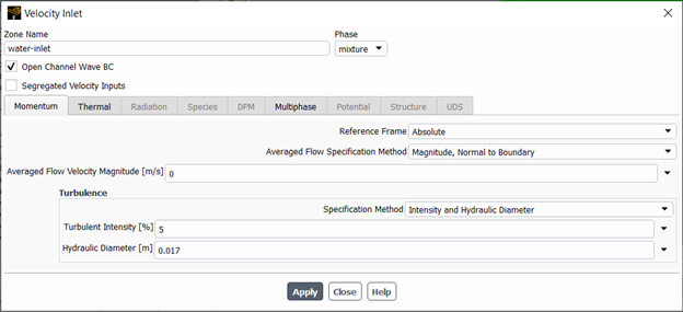
Figure 9: The choice of wave theory depends on the wave’s properties. This chart helps engineers select the most accurate model for their simulation
For more advanced control, especially when a moving object or separate currents are involved, you can use Segregated Velocity Inputs. This allows you to define the velocity for the water, air, and any moving object separately.
- Moving Object Velocity Inputs: Sets the speed of a moving reference frame, like a ship hull moving through the water.
- Secondary Phase Velocity Inputs: This is where you set the velocity for the water phase.
- Primary Phase Velocity Inputs: This is where you set the velocity for the air phase.
For each of these, you define the Velocity Specification Method (e.g., Magnitude, Normal to Boundary) and the Velocity Magnitude [m/s].
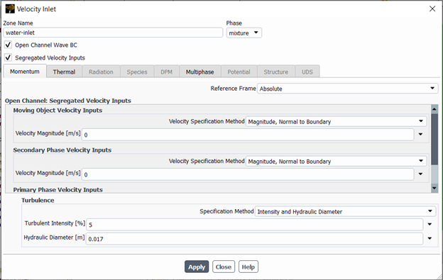
Figure 10: Using Segregated Velocity Inputs in the Momentum tab to define separate velocities for the water, air, and a moving object in an open channel wave simulation
Advanced Modeling: Simulating Moving Objects
In many engineering problems, we need to understand how an object moves in the water. For example, how does a boat move in waves, or how does a floating platform behave in the ocean? The main challenge is that when an object moves, the mesh (the grid used for calculations) around it must also change. We solve this using the Dynamic Mesh model. This highly adaptable tool allows the mesh to stretch, deform, and rebuild itself as the object moves.
To predict the object’s movement, we use the 6DOF (Six Degrees of Freedom) Solver. The name 6DOF means the object is free to move in all six directions: forward/back, up/down, side-to-side, and also rotate in three ways (roll, pitch, and yaw). The 6DOF solver calculates the forces and torques the water puts on the object and then moves the object realistically in response.
By combining the VOF approach for free surface modeling, the 6DOF solver for movement, and the Dynamic Mesh for the changing grid, we can accurately simulate structural interactions. A perfect example is modeling a boat’s motion on a wavy sea. You can see a complete practical tutorial on this topic in our Floating Boat on Water CFD Simulation product. Our library has many 6DOF dynamic mesh tutorials for anyone who wants to search deeper in this field of study.

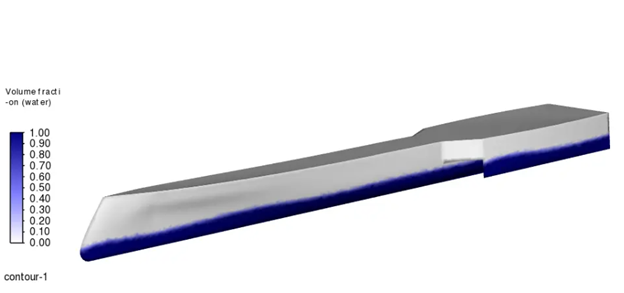
Figure 11: Simulating a floating body requires advanced tools. The 6DOF solver predicts the body’s motion, while the Dynamic Mesh updates the grid around it to handle the movement
Conclusion
In this guide, we have explained the essential steps for performing an open channel flow simulation in ANSYS Fluent. We learned to accurately capture the free surface between water and air. Understanding the physics, especially the Froude Number, is necessary for classifying the flow and setting up a meaningful simulation.
We also saw that choosing the correct CFD wave theory, from simple linear models to more adaptable non-linear ones, is highly important for getting realistic results in marine and coastal simulations. These advanced features allow us to simulate real-world problems, such as predicting the motion of a floating boat in waves. By using these methods, we can analyze everything from river flows and dam safety to the design of ships and offshore structures. CFD simulation gives us a reliable way to understand and solve heavy challenges in hydraulic and marine engineering. In case you still have issues with your project, you can assign for a CFD consultation meeting before ordering your CFD project to our experts.