

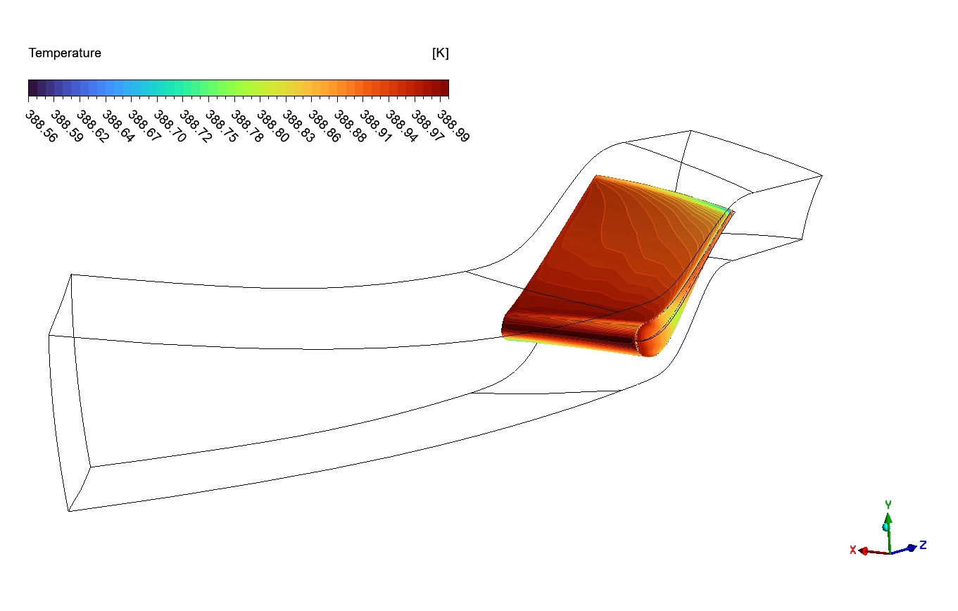
Power plants use high-speed gas to spin large turbine blades and generate electricity. The gas must flow smoothly through the machine to create maximum power. Specialists use an axial turbine CFX simulation to study these internal flows before building the real parts.
This ANSYS training helps you understand how physical pressure converts into fast kinetic energy. We analyze the nozzle passage to ensure a highly efficient turbine design. This saves time and provides accurate physical results for rotating machinery.
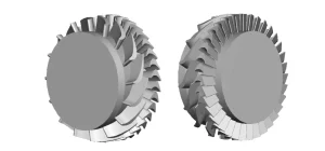
Figure 1: The complete multi-stage axial turbine designed for high-power energy generation [Han et al.].
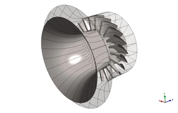
Figure 2: Our full geometry model of axial turbine nozzle
Simulation Process: Blade Design in Axial Turbine CFD Project
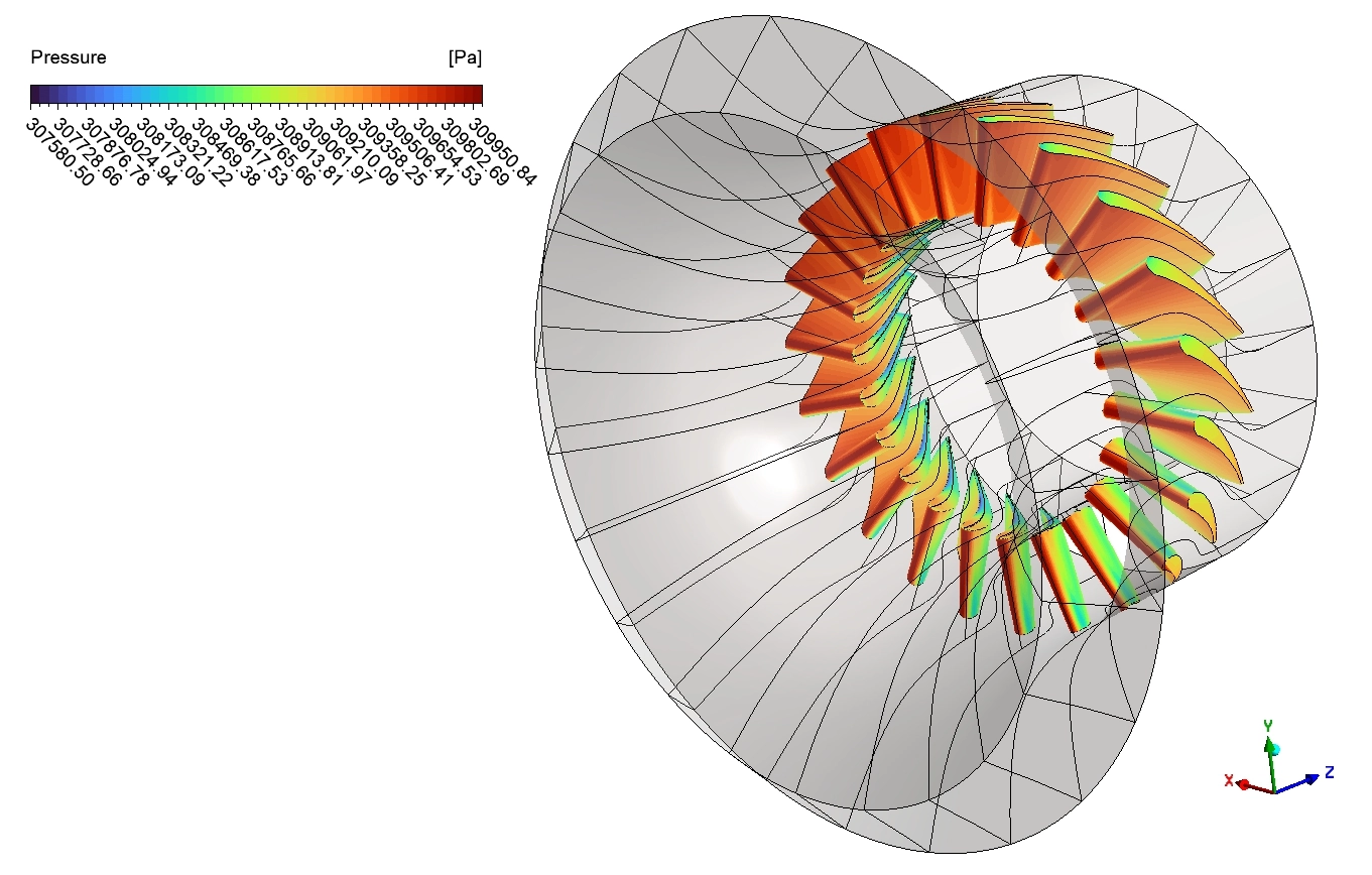
We do not need to calculate the entire circular engine. We design one single nozzle blade using the Bladegen tool. We then apply a periodic boundary condition to spin this single piece into a full 360° model. This method saves calculation time while providing true physical results. You can learn more about rotating symmetry in our turbomachinery CFD simulation trainings.
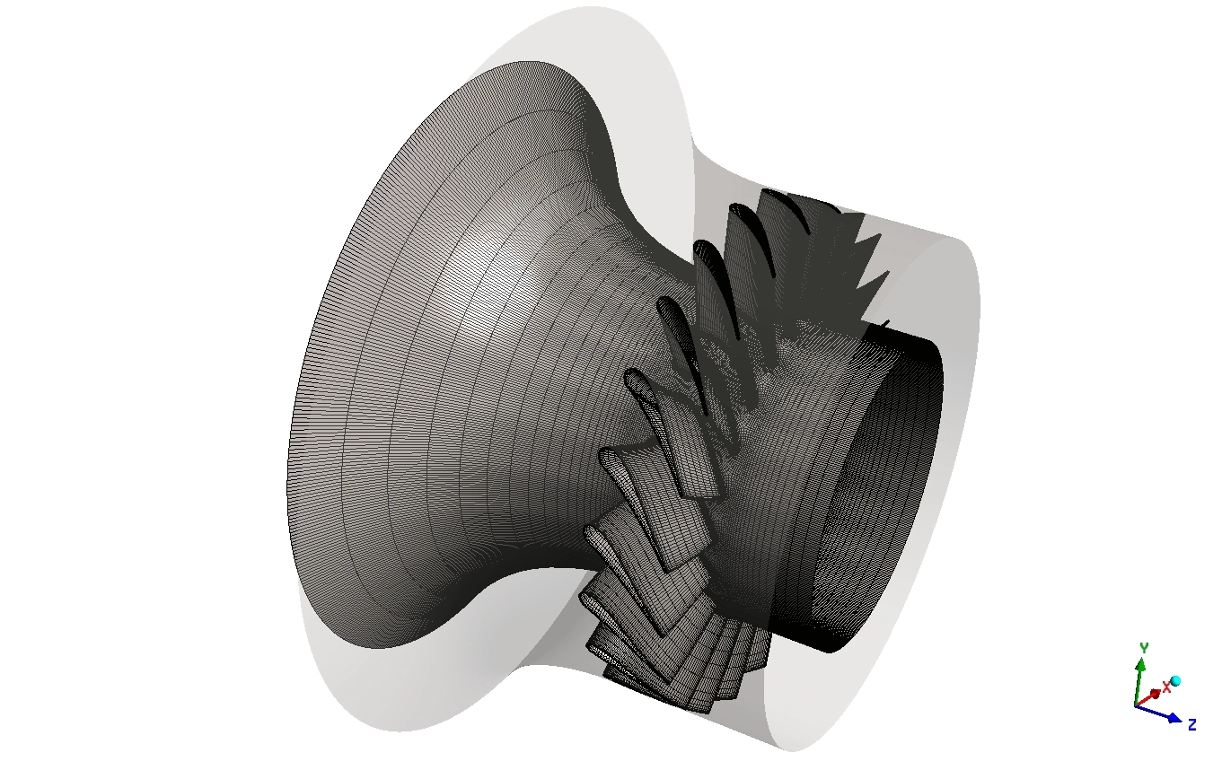
Creating a high-quality grid is critical for rotating machinery. We use Turbogrid to cut the fluid space into a fully structured hexahedral mesh containing 126,200 cells. This specific cell shape calculates the physical fluid forces very accurately. We then solve the mathematical model using CFX, which handles rotating parts perfectly.
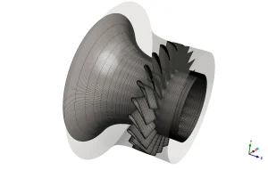
Figure 3: The fully structured mesh dividing the fluid space into tiny calculation cells.
Post-processing: Flow Physics and Kinetic Energy Conversion
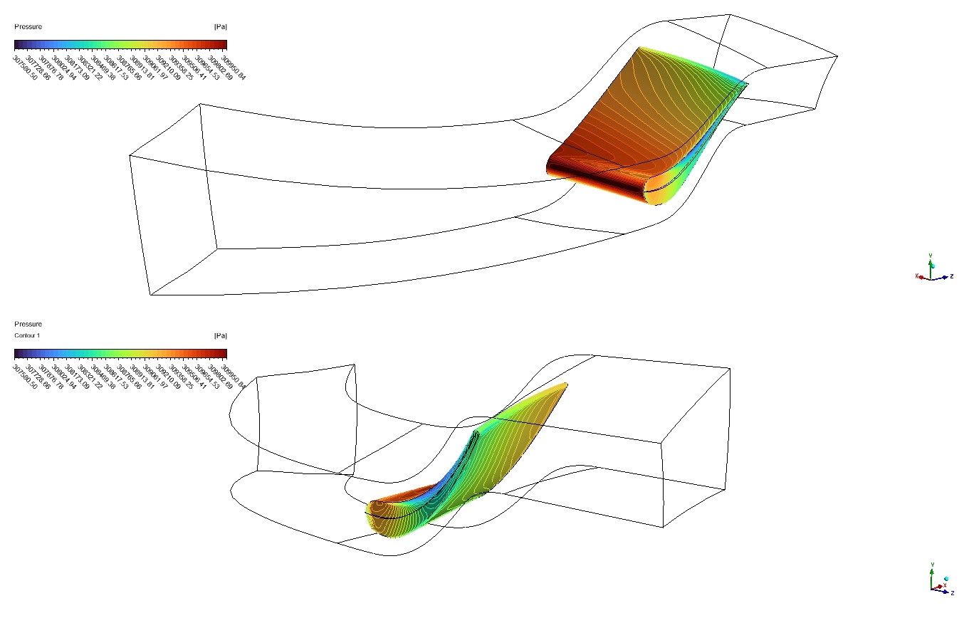
We start by analyzing the physical pressure contours to see how the gas pushes against the solid blades. The pressure drops smoothly and evenly from the front inlet to the back outlet. There are no sudden changes or flow separation on the metal walls. This proves the gas enters the turbine nozzle in a very stable and well-organized manner.
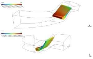
Figure 4: The internal pressure distribution across a single turbine nozzle passage.
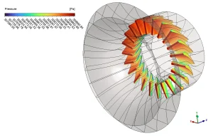
Figure 5: Full 360° nozzle mesh reconstructed from one periodic passage, showing pressure distribution on the blade surface.
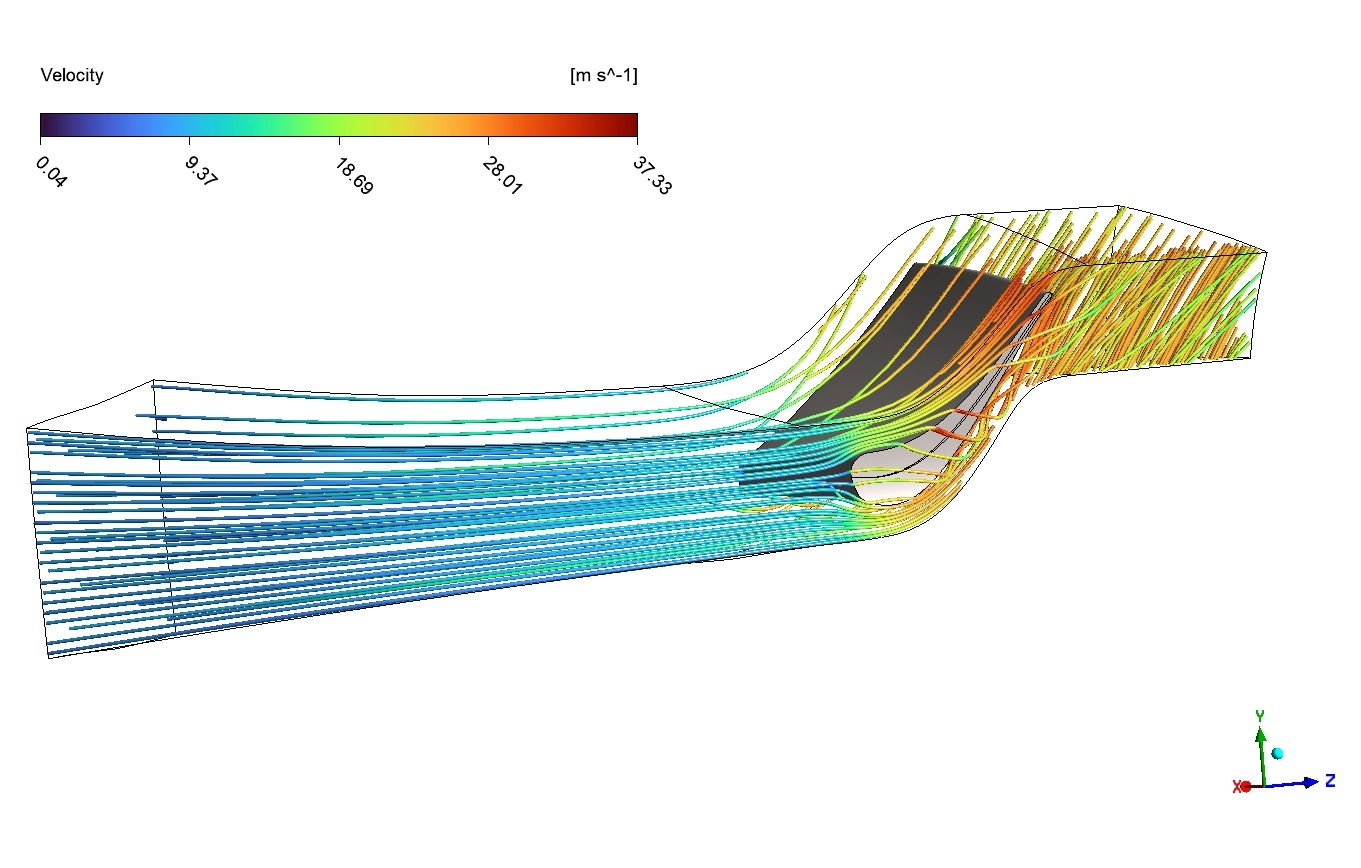
The velocity streamlines show the true physical purpose of the nozzle. The gas enters the passage at a slow speed of 9 m/s. As the channel physically narrows, it squeezes the fluid. The gas accelerates rapidly, reaching a high exit speed of 37 m/s. This rapid acceleration proves that the nozzle successfully converts high internal pressure into fast-moving kinetic energy. This fast gas will then hit the next set of spinning rotor blades with maximum physical force.
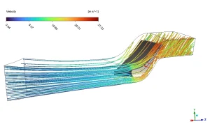
Figure 6: The fluid streamlines demonstrating rapid kinetic energy conversion at the blade exit.
FAQ About Axial Turbine CFX Physics
- Why do we use a periodic boundary condition? A turbine is a repeating circle of identical blades. Instead of calculating the whole circle, we calculate just one blade passage. The periodic boundary condition mathematically copies this result in a circle, giving us the full physical picture instantly.
- Why does the gas speed up inside the nozzle? The space between the blades gets smaller near the exit. When a fluid is pushed into a smaller space, it must travel faster to get through. This physical squeezing converts the high gas pressure into high-speed kinetic energy.






Reviews
There are no reviews yet.