

In marine engineering, the propeller is the most important component of a ship. The main job of a propeller is to convert the rotational energy from the ship engine into a forward pushing force. This forward force is called thrust. To design a highly efficient cargo ship or submarine, engineers must understand exactly how water moves around the complex curved blades. In the past, researchers tested physical metal models in large water tanks. Today, researchers use a computer method called Thrust of Marine Propeller CFD to study the water flow digitally. By performing a Thrust of Marine Propeller fluent simulation, a designer can calculate the exact forces acting on the blades before the factory builds the real object. This CFD Analysis of Thrust of Marine Propeller is a highly valuable tool for marine engineering. It helps researchers find the optimal blade shape to reduce fuel consumption and improve speed. Inside the computer software, engineers can measure important parameters such as the marine propeller thrust coefficient calculation and the propeller efficiency calculation ANSYS Fluent. Because a propeller spins very fast, the computer must use special rotating mathematical zones to solve the physics equations correctly. To learn the exact steps for setting up these rotating computer frames for your own engineering projects, please study our detailed MRF tutorials.
- Reference [1]: Sezen, Savas, and Omer Kemal Kinaci. “Incompressible flow assumption in hydroacoustic predictions of marine propellers.” Ocean Engineering186 (2019): 106138.

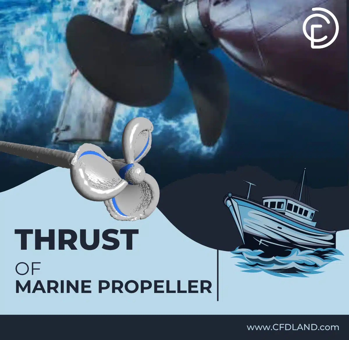
Figure 1: A physical marine propeller, showing the curved metal blades designed to generate forward thrust in water.
Simulation Process: Poly-Hex Meshing and MRF Setup in ANSYS Fluent
To begin this Thrust of Marine Propeller ANSYS Fluent project, we prepared a 3D model of the well-known DTMB-4119 propeller. This specific model has a radius of 0.25 meters. We placed this digital propeller inside a large cylindrical computer domain filled with liquid water. Next, we used the Fluent meshing tool to divide the water volume into exactly 5,862,460 cells. We selected poly-hex cells for this study. Polyhedral cells are very efficient for marine shapes because they conform easily to the curved blade surfaces and help the computer solve the equations faster.
To simulate the physical rotation of the propeller, we applied the Multiple Reference Frame (MRF) method inside the Thrust of Marine Propeller fluent software. The MRF method creates a rotating mathematical zone around the blades. We set the rotational speed to exactly 2146 RPM, which equals 35.77 revolutions per second. We also programmed the incoming water to enter the domain at an advance velocity of 2.15 m/s. The software then calculated the steady-state fluid equations to determine the final forces and fluid behaviors.
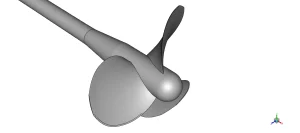
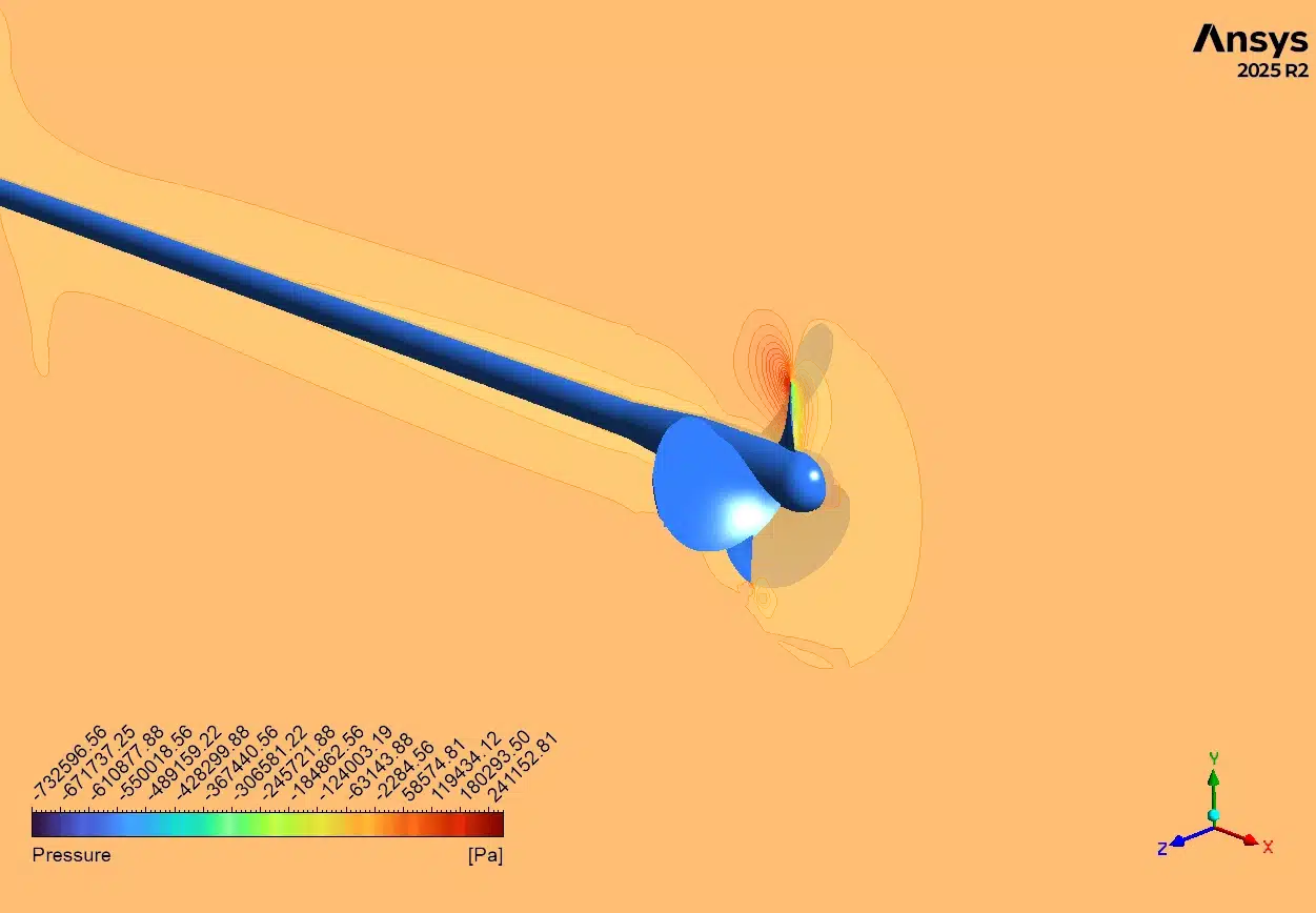
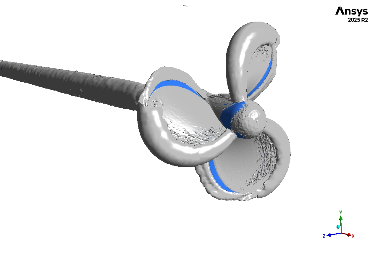
Figure 2: The 3D computer geometry, displaying the DTMB-4119 propeller and the rotating boundary zone.
Post-processing: Analysis of Hydrodynamic Forces and Open-Water Efficiency
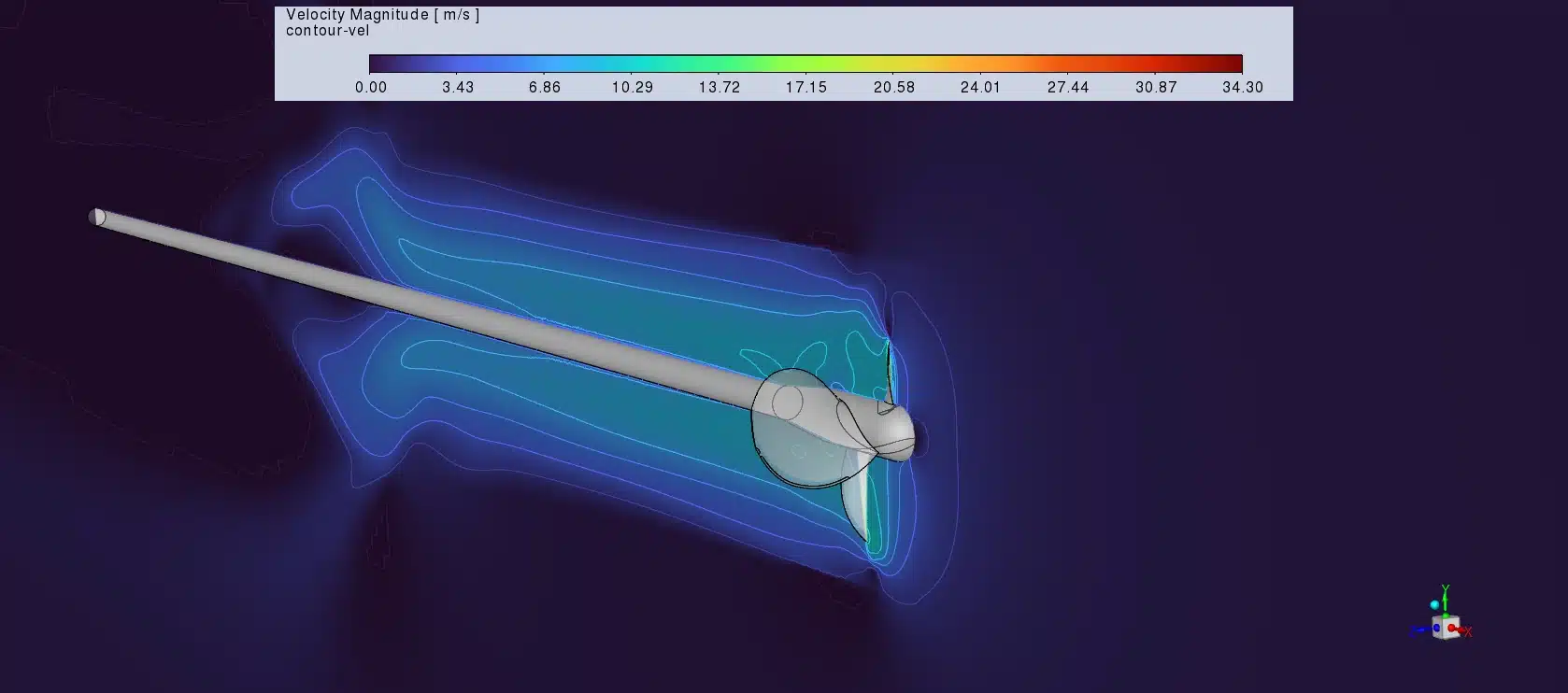
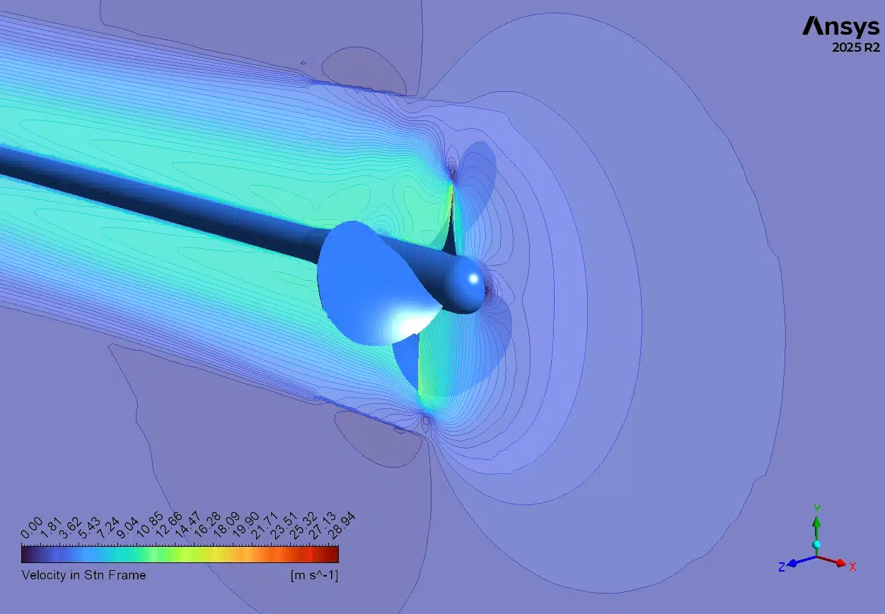
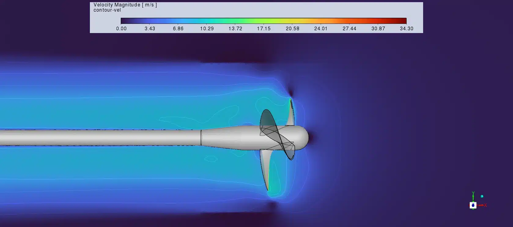
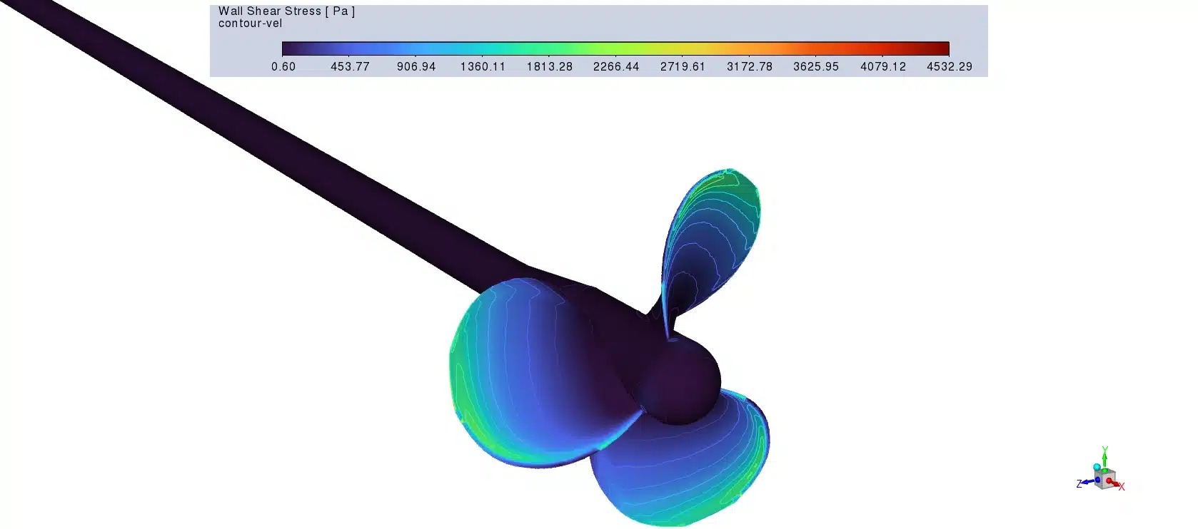
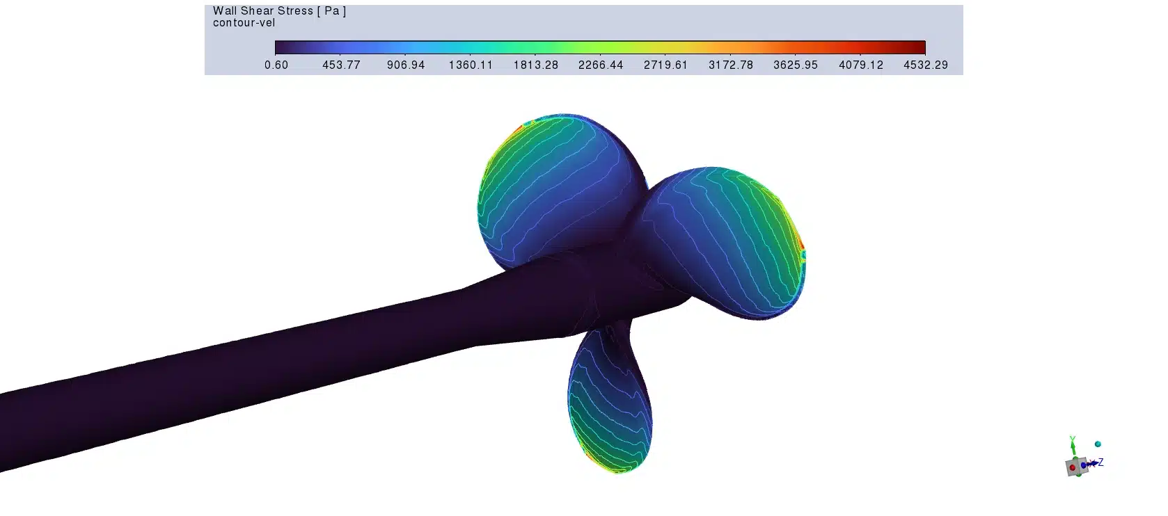
To completely understand the propeller design, we must study the exact computer data and the velocity contours. This scientific analysis explains how the blades change the water speed and how much mechanical energy the engine needs. First, we look at the velocity magnitude contours. On the front side of the blades, the water color is green and cyan. This indicates a safe, moderate water speed of 10 to 17 m/s. However, the fluid physics changes completely on the back of the blades. Engineers call this the suction side. The computer displays bright red colors exactly at the blade tips. These red zones show that the water moves very fast, reaching up to 34.30 m/s. In fluid mechanics, fast water creates low static pressure. If the water pressure drops below the natural vapor limit, small vapor bubbles form on the metal surface. This physical problem is called cavitation. Cavitation is very bad for marine propellers because the bubbles collapse and slowly destroy the solid metal. By seeing these red high-speed zones, a designer can flatten the blade curve to slow down the water and stop cavitation.
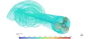
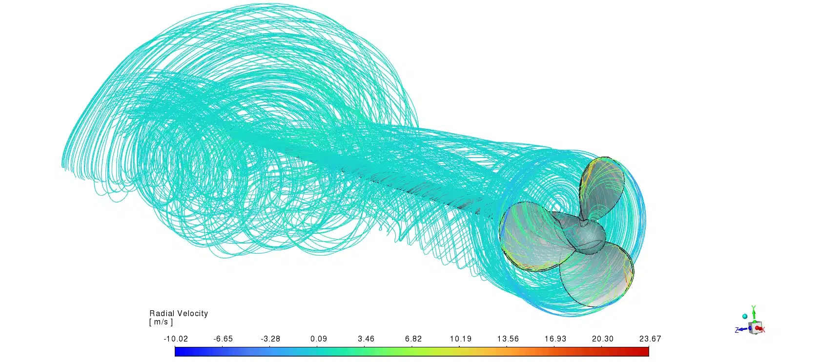
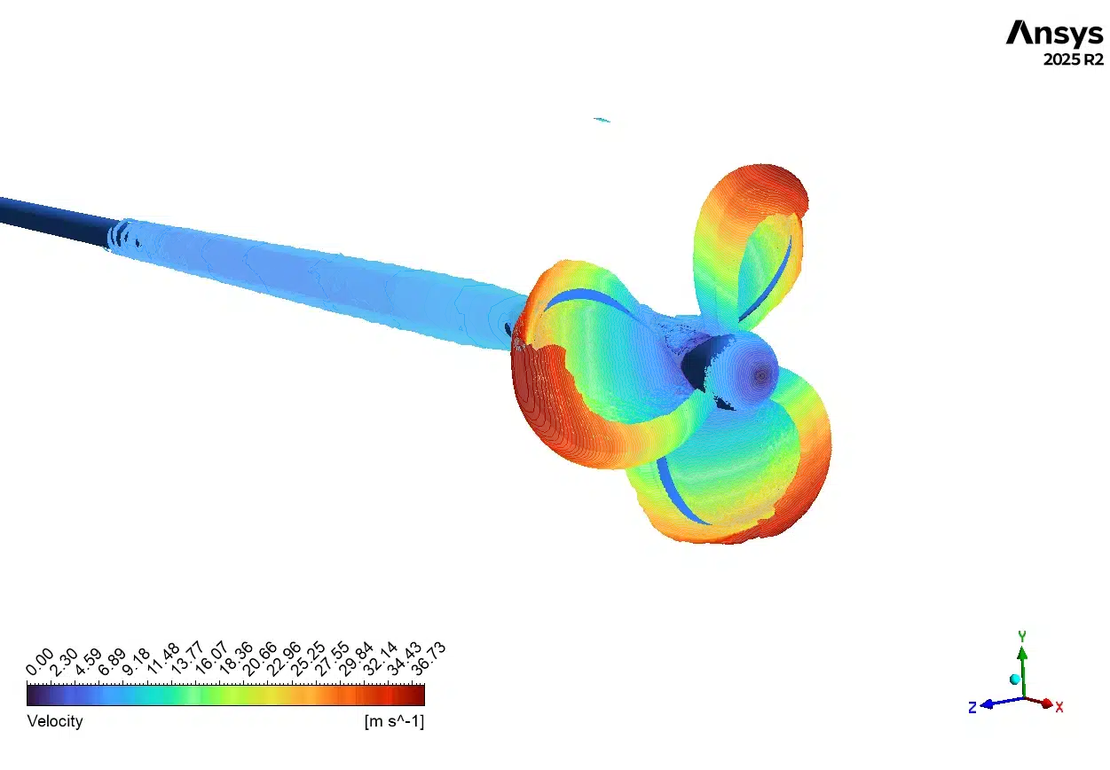
Figure 3: Streamlines colored by velocity, showing the twisting wake field as the water leaves the rotating blades.
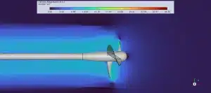

Figure 4: Velocity magnitude contours, displaying the high-speed red zones (34.30 m/s) at the tips and the slower blue zones near the hub center.
Next, we study the exact mechanical forces. The software calculates non-dimensional numbers called coefficients to measure the performance. The computer calculated the exact thrust coefficient (kt) to be 0.29529756. This number represents the total forward pushing power of the blades. At the same time, the computer calculated the exact torque coefficient (kq) to be 0.061189746. This number measures the twisting resistance of the heavy water. The ship engine must be strong enough to beat this resistance to keep the propeller spinning. These coefficients are highly accurate and very useful for the factory builders to select the correct engine size.
Table 1: Exact Hydrodynamic Coefficients and Open-Water Efficiency
| Hydrodynamic Parameter | Computer Variable | Calculated Value |
| Advance Coefficient | 0.201 | |
| Thrust Coefficient | 0.29529756 | |
| Torque Coefficient | 0.061189746 |
Finally, we use these coefficients to calculate the open-water efficiency (η0) of the propeller. The efficiency formula connects the advance coefficient (J), the thrust coefficient (kt), and the torque coefficient (kq). In our specific simulation, the advance coefficient is . The advance coefficient compares the slow forward speed of the ship to the fast spinning speed of the blades. To find the open-water efficiency, we multiply by , and then we divide that result by . Using our exact data, the mathematical result is an open-water efficiency of 15.4%. In academic marine studies, 15.4% is a low but completely correct number for a low advance coefficient (J). A low means the ship is moving forward very slowly, but the engine is working very hard. This happens in real life when a ship is pulling a very heavy load. The simulation data proves that this propeller design generates strong physical forces and works perfectly for a heavy towing ship.
Frequently Asked Questions (FAQ)
- Q: What is the MRF method in a marine CFD simulation?
- A: MRF stands for Multiple Reference Frame. It is a mathematical tool in ANSYS Fluent that allows the computer to simulate a spinning object, like a propeller, without physically moving the computer mesh. It saves calculation time.
- Q: Why does the water speed increase so much on the back of the blade?
- A: The propeller blades have a specific curved shape, similar to an airplane wing. As the blades push through the water, this curve forces the water to travel a longer distance over the back surface, which causes the water to accelerate.
- Q: What are the and coefficients?
- A: The value is the thrust coefficient. It shows the forward pushing force of the blades. The value is the torque coefficient. It shows the water resistance that the engine must fight to turn the propeller.
- Q: How do you calculate open-water efficiency?
- A: Open-water efficiency (η0) is calculated using the advance coefficient (J), the thrust coefficient (kt), and the torque coefficient (kq). You multiply and , and divide by . For , the efficiency is 15.4%.


Reviews
There are no reviews yet.