

Welcome to this engineering tutorial. Large marine ships carry liquid natural gas across the ocean. When the ship moves on the sea waves, the heavy liquid inside the tank moves too. Engineers call this violent motion sloshing. When the liquid sloshes, it crashes into the metal walls of the tank. This crash creates a massive physical force. Over time, this repeating force can break the tank walls and cause a very bad accident on the water.
Engineers cannot easily test a real moving ship to see these dangers. Instead, we use ANSYS Fluent to model all simulations here. This software helps us see the exact wave shape and the true crash force. By studying a professional dynamic mesh CFD simulation, engineers can learn how to design stronger tanks and keep marine ships safe.
- Reference [1]: Lu, Zhimei, et al. “Numerical Simulation and Optimization Study of Liquid Sloshing in a LNG Storage Tank.” Journal of Marine Science and Engineering6 (2026): 525.
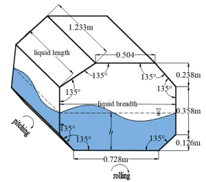
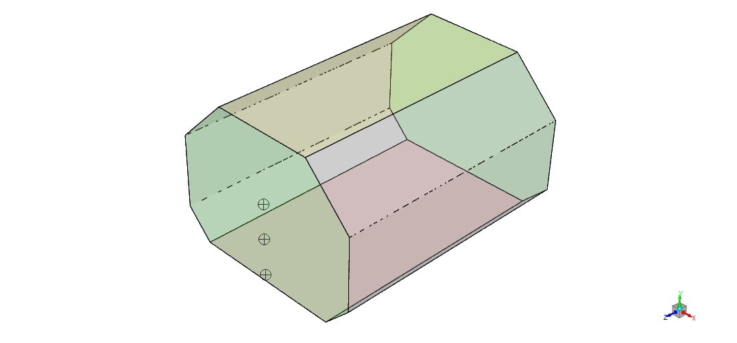
Figure 1: A sketch showing the exact geometry and walls of the LNG tank used for this ANSYS Fluent tutorial. [1]
Simulation Process: Polyhedral Mesh and Dynamic Motion
To solve this fluid problem in our tutorial, ANSYS Fluent needs a very smart mathematical grid. The mesh uses exactly 559,829 polyhedral cells. Because they have more faces, ANSYS Fluent calculates the exact pressure much better when the heavy liquid hits the flat wall.
The tank must move exactly like a real ship on ocean waves. To create this motion, the simulation uses a User Defined Function code. This code applies a pitch (front-to-back) velocity and a roll (side-to-side) velocity at the same exact time. The math uses a cosine wave formula to create a smooth, repeating ocean motion. Thus, Dynamic Mesh module is needed to implement the motion on the LNG tank. As the tank rocks, the Volume of Fluid model tracks the exact line between the heavy liquid and the empty gas.
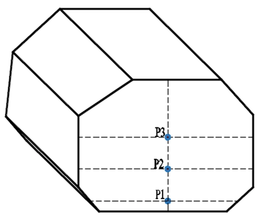
Figure 2: A diagram showing the exact testing points at 1 cm, 19 cm, and 36 cm heights to measure wall forces.
Post-processing: Analyzing Extreme Wave Velocity and Pressure
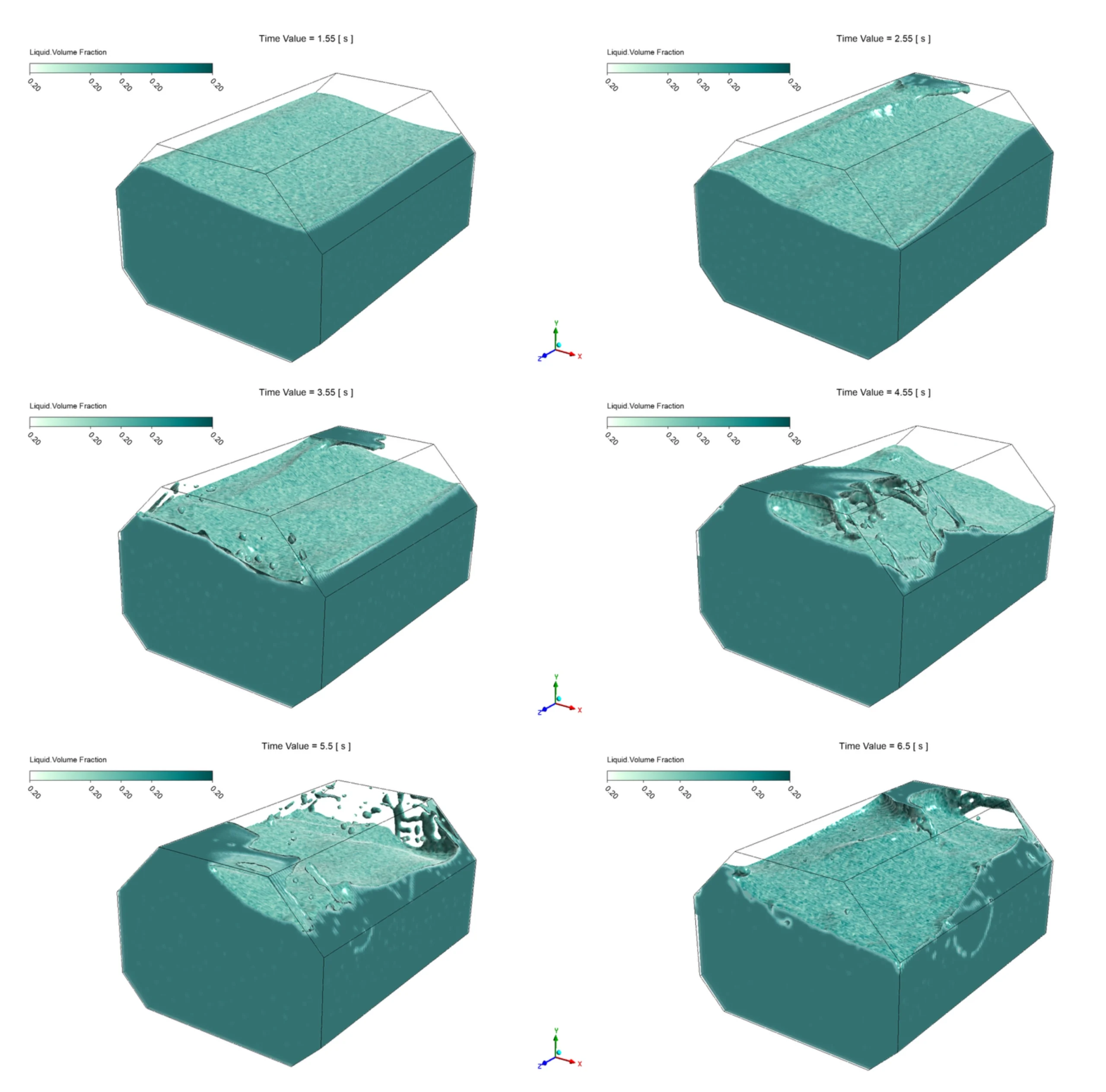
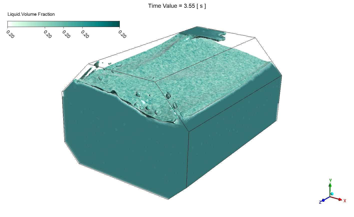
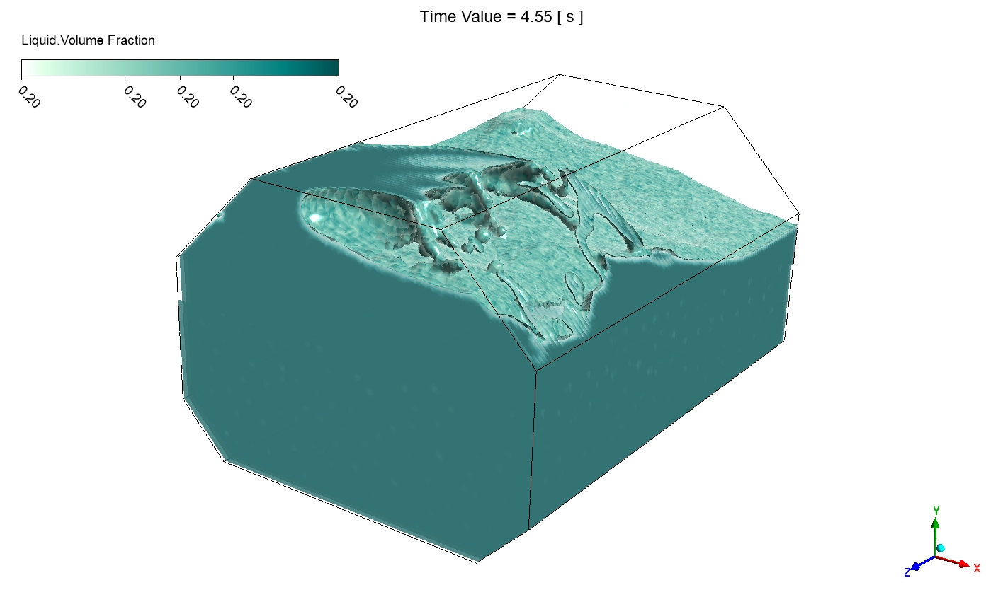
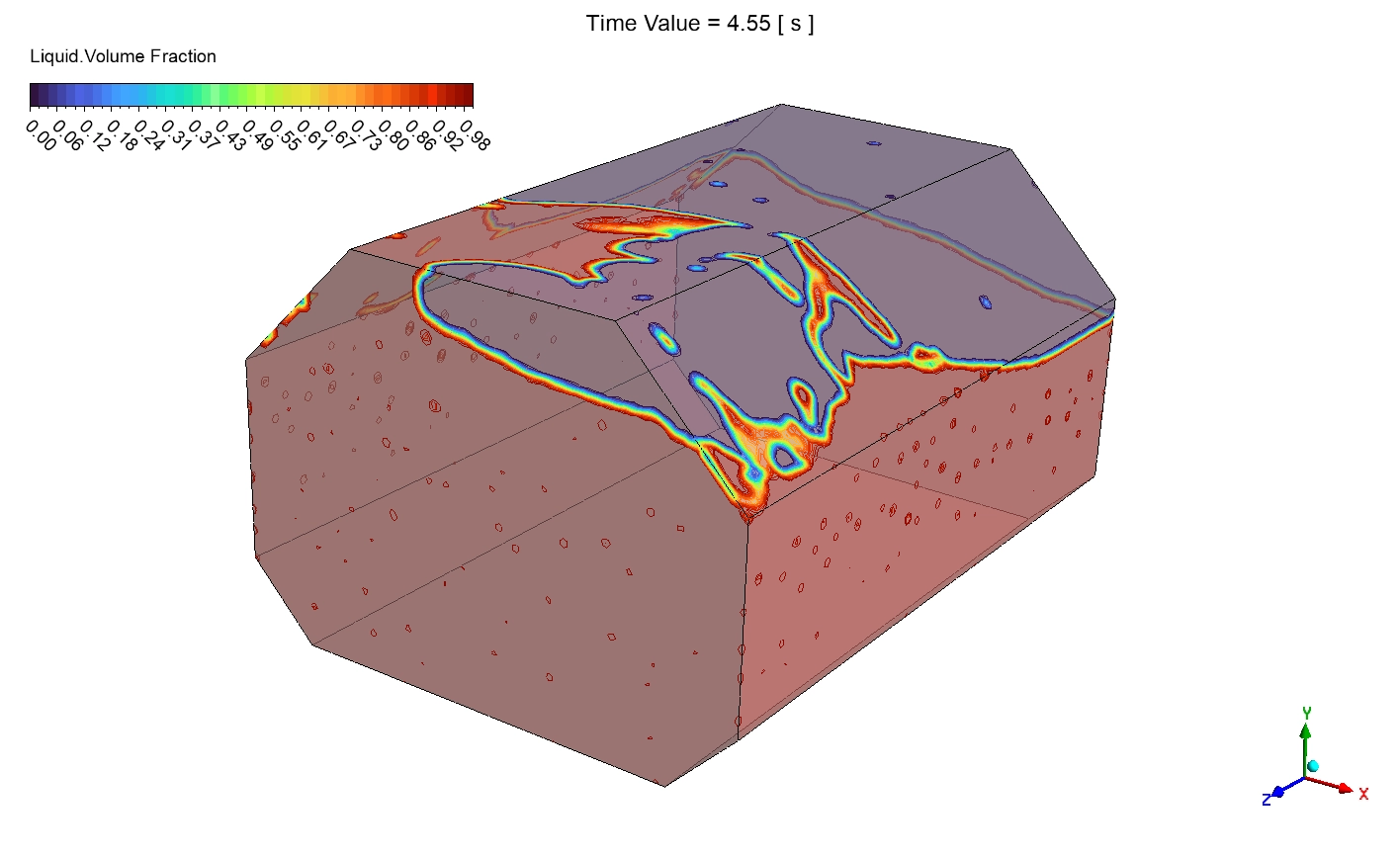
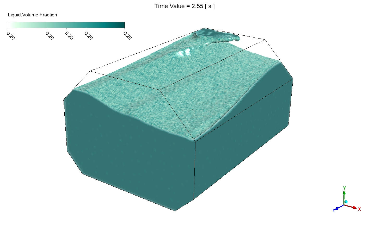
Now we will look at the visual data to understand the exact physics of the crash. We will study the shape of the liquid, the velocity of the wave, and the exact pressure on the tank wall. First, we look at the liquid volume fraction contours. The dark color is the liquid, and the light color is the empty gas. At exactly 1.55 s, the tank has a 50 % filling level. The liquid surface is very flat. This is the most dangerous filling level because the wave has enough room to grow big. At 2.55 s, the tank rolls. The liquid climbs the right wall at an angle of about 15 degrees. At 3.55 s, the pitch and roll motions mix. This creates a complex 3D wave that pushes high into the corner.
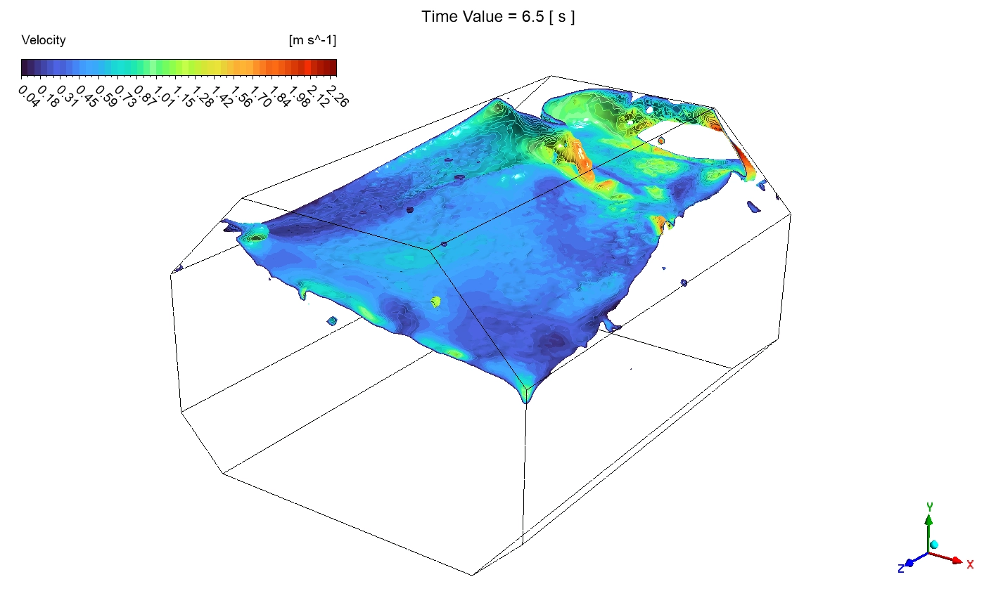
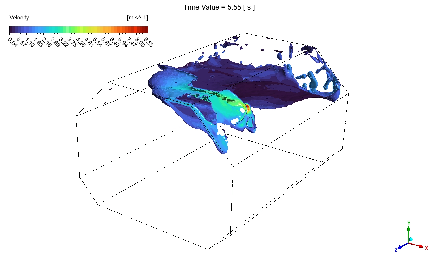
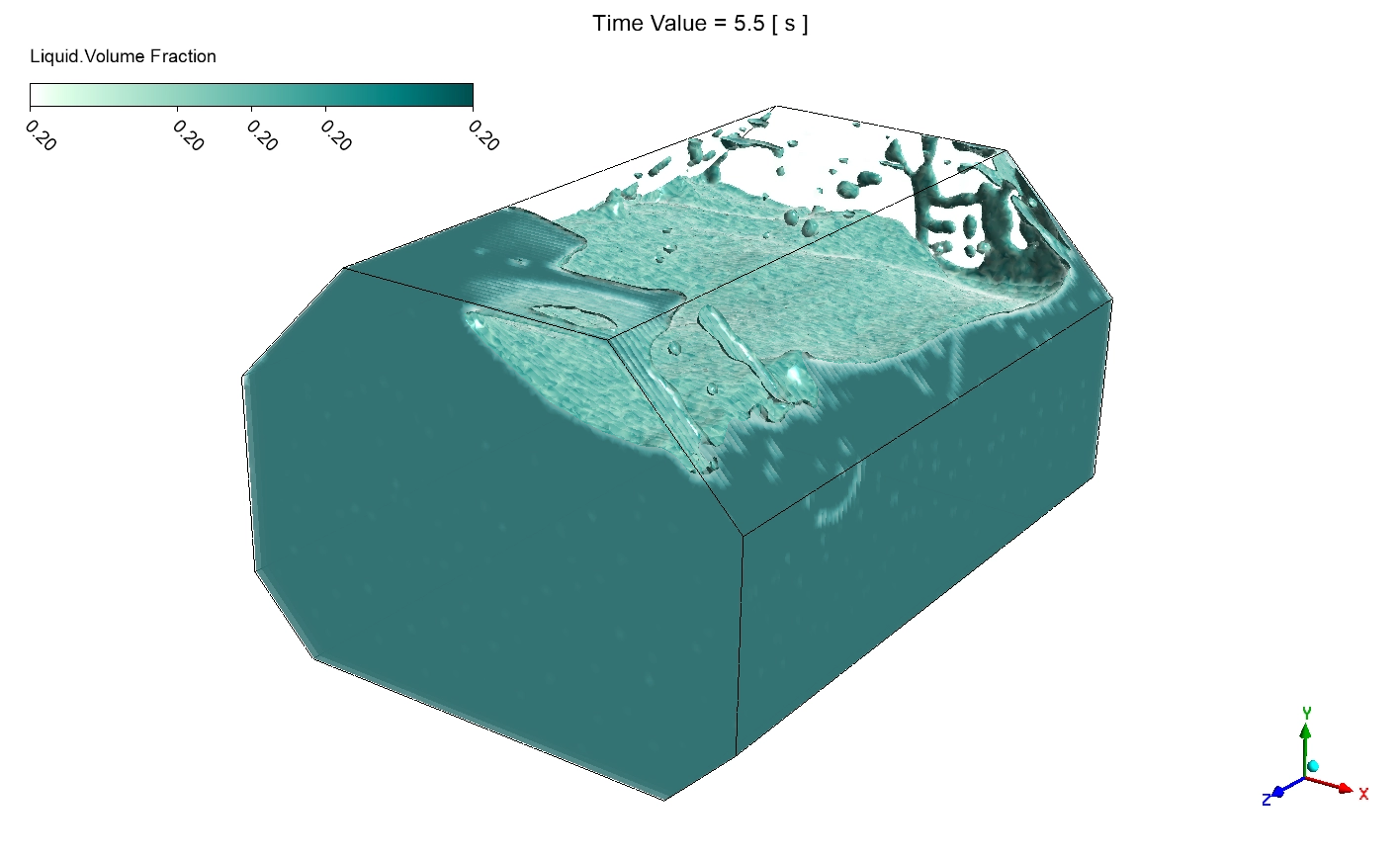
The worst damage happens between 4.55 s and 5.55 s. The big wave completely breaks apart. The heavy liquid flies through the air and crashes into the top roof. At exactly 5.55 s, about 20 to 30 % of the tank roof is hit directly by the heavy liquid. By 6.5 s, the tank rolls back, and the broken wave falls down, leaving a very rough liquid surface.
We can see the true danger of this crash in the velocity contours. At 1.55 s, the liquid moves very slowly. The absolute maximum velocity is only 0.40 m/s. As the wave climbs the wall at 3.55 s, the maximum velocity grows to 1.98 m/s. Then, the massive roof crash happens. At exactly 5.55 s, the fluid speed jumps to an absolute maximum of exactly 8.53 m/s. This high-speed water carries huge energy. When it hits the solid roof, it stops instantly, turning all that speed into a crushing physical force. By 6.5 s, the wave falls down, and the top velocity drops to 2.26 m/s.
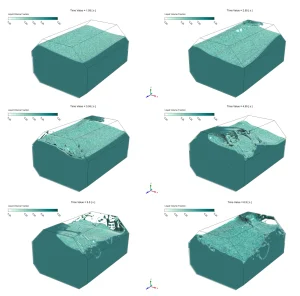
Figure 3: The volume fraction liquid contours from 1.55 s to 6.5 s, showing the heavy wave crashing on the roof.
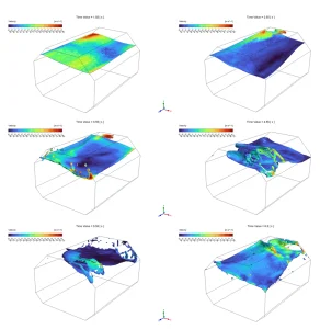
Figure 4: The velocity surface contours mathematically proving the fluid speed reaches a maximum of 8.53 m/s at 5.55 s.
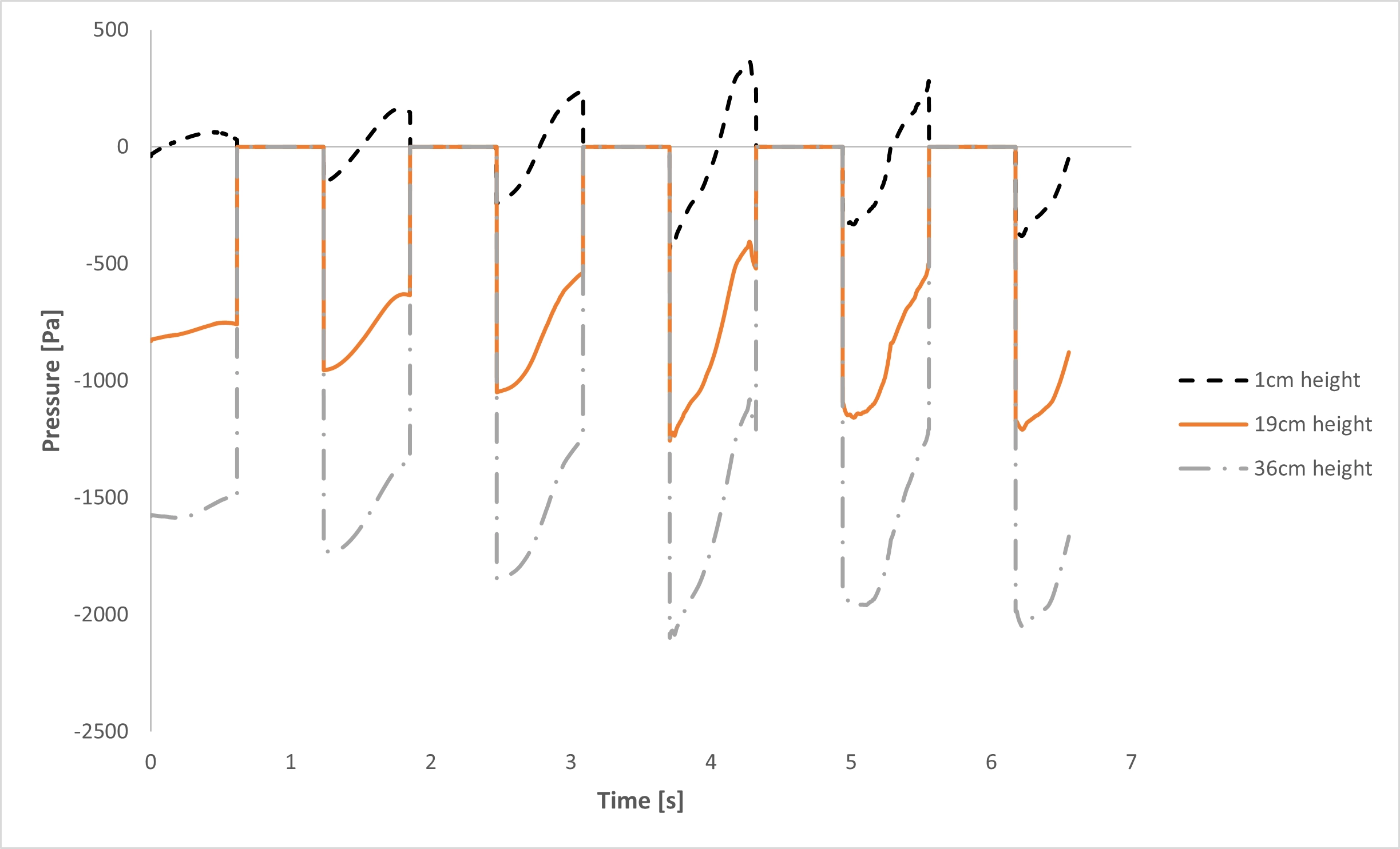
Finally, the pressure line graph proves exactly how much force hits the walls. The graph measures pressure at three exact heights: 1 cm, 19 cm, and 36 cm. The black dashed line is the floor at 1 cm. It stays under the liquid safely, feeling a maximum positive pressure of about 350 Pa. The orange solid line tracks the middle wall at 19 cm. The pressure here drops down to a suction of -1200 Pa.
The true danger is at the top of the tank. The gray dash-dot line shows the pressure near the roof at a 36 cm height. When the heavy liquid wave falls away from the roof, it pulls the empty gas down with it. The graph proves this creates a massive suction vacuum of exactly -2100 Pa. Then, when the wave crashes back up, the pressure instantly spikes up to 400 Pa. This violent swing from pulling to pushing happens every 1.4 s, matching the ocean wave timing. This exact repeating force bends the metal until it breaks.
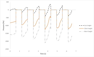
Figure 5: The pressure graph showing the massive wall suction reaching exactly -2100 Pa at the top height.
Frequently Asked Questions (FAQ)
- Why do we use the VOF and Dynamic Mesh modules?
- The VOF module is perfect for tracking the exact line where the liquid and gas touch. The Dynamic Mesh module is needed to move the tank walls just like a real ship moving on ocean waves.
- What does a pressure of -2100 Pa mean for the tank?
- Negative pressure is a suction vacuum. When heavy water hits the roof and then drops very fast, it pulls on the roof. This strong pulling force of -2100 Pa can rip the walls apart over time.
- Why is the 8.53 m/s velocity so dangerous?
- Liquid gas is very heavy. When a heavy mass moves at a very fast velocity, it carries a huge amount of energy. When that fast liquid hits the solid roof, it stops in one second. All that speed turns into a strong physical hammer.


Reviews
There are no reviews yet.