
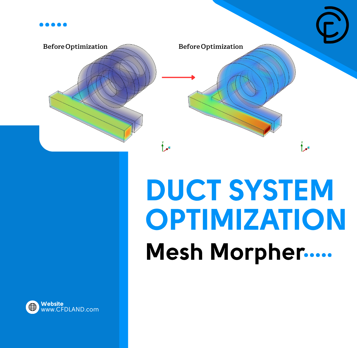

In modern ventilation design, engineers face strict energy and flow limits. A poor duct shape causes severe flow imbalance and wastes mechanical energy. We cannot rely on manual trial and error to fix complex fluid systems. Instead, we use advanced computational shape optimization. This mathematical approach automates design improvements without manual human drawing.
The software uses intelligent morphing tools to deform the physical boundaries until the perfect flow is achieved. If you plan to master these advanced methods, studying our professional HVAC CFD simulation projects is a required step. In this tutorial, we will use the Mesh Morpher and Optimizer in ANSYS Fluent. We will deploy this tool to automatically deform the solid walls of a bifurcated duct. You will learn the exact fluid physics required to balance complex mass flow distribution correctly.
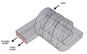
Figure 1: Geometry outline on initial model
Simulation Process: Optimization Objective
To evaluate the flow physics, we study a duct with one straight channel and one complex helical branch. The initial base design fails to balance the mass distribution. The fluid completely ignores the high-resistance spiral path. We activate the shape optimization physics to fix this structural failure.
We instruct the Optimizer to balance the fluid exit targets. We define specific control points on the solid floor. The Mesh Morpher takes these points and translates them into physical wall displacements. It bends and stretches the existing 38,500 hexahedral mesh cells without requiring a completely new grid. The solver tests different geometric shapes continuously. This iteration repeats until the physical floor shape forces the fluid to distribute evenly between the two separate paths.
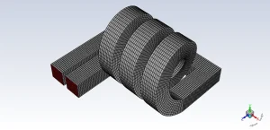
Figure 2: Fully structured grid upon the basic model
Post-processing: Physics of Shape Morphing and Flow Redirection
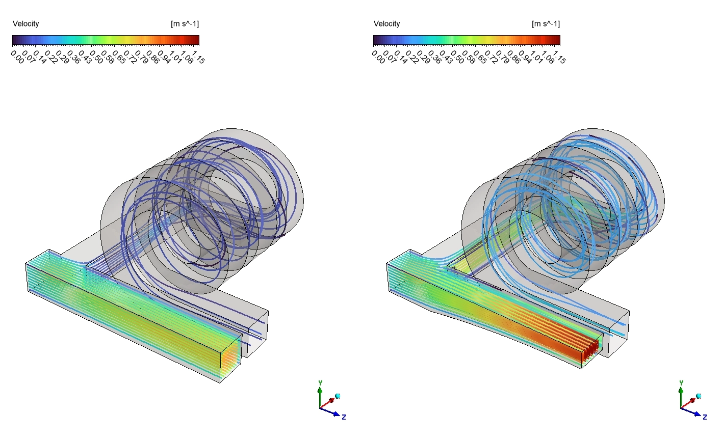
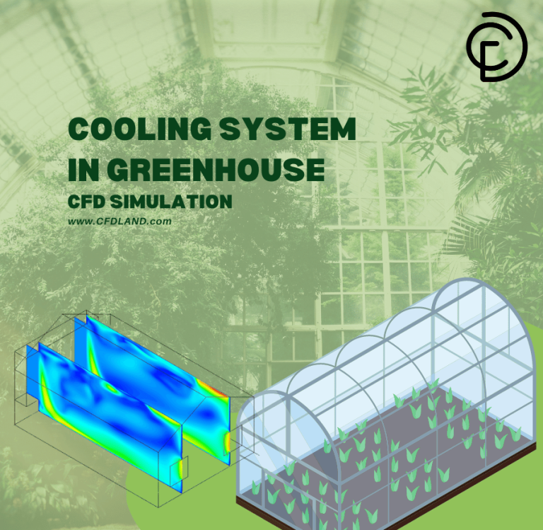
We must analyze the visual flow fields to understand the exact shape optimization physics. We compare the base geometry on the left to the morphed geometry on the right. The visual data proves how the automated wall deformation directly controls the fluid path. We will study the fluid speed and the physical pressure barriers strictly based on the provided visual contours.
We begin by examining the three-dimensional Velocity contour in the first visual. The legend defines the speed scale from exactly 0 to 1.15 [m s^-1]. In the base model on the left, the helical branch is completely covered in dark blue. This dark color indicates the local fluid Velocity is near exactly 0 [m s^-1]. The fluid refuses to enter the spiral path because the straight channel offers zero resistance. When we observe the right image, we see the Mesh Morpher has severely altered the main floor. The solid bottom wall slopes upward to create a physical ramp. This automated shape optimization completely transforms the helix flow. A bright red and orange fluid core appears at the helix exit. The Velocity inside the spiral jumps to the maximum limit of exactly 1.15 [m s^-1]. The fluid now successfully navigates the complex twisted boundary.
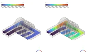
Figure 3: The 2D Pressure contour proving the mesh morpher creates a localized 1.01 [Pa] barrier to divert the fluid.

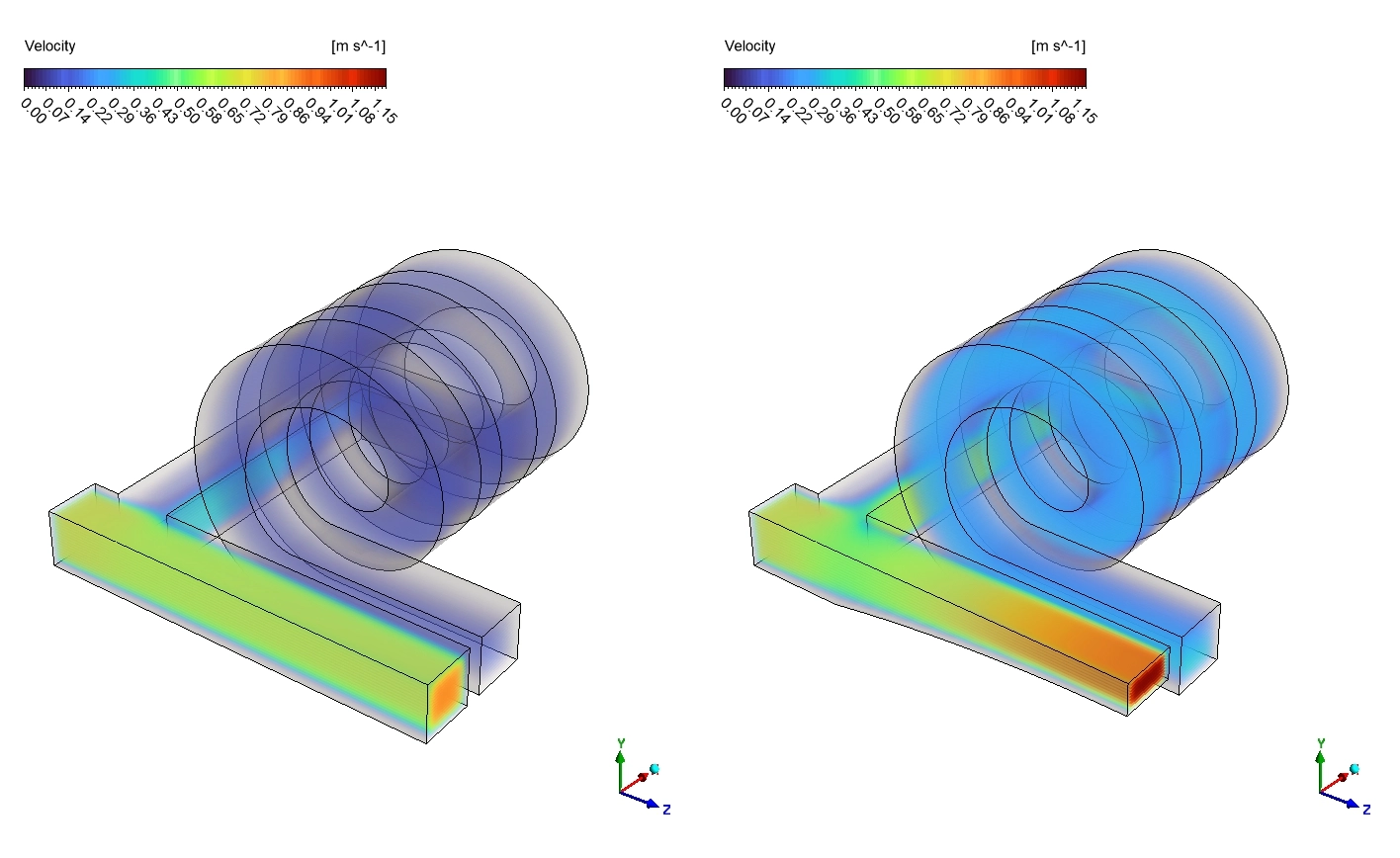
Figure 4: The Volume Rendering Velocity contour showing the helix accelerating from 0.00 to 1.15 [m s^-1] after the shape optimization.

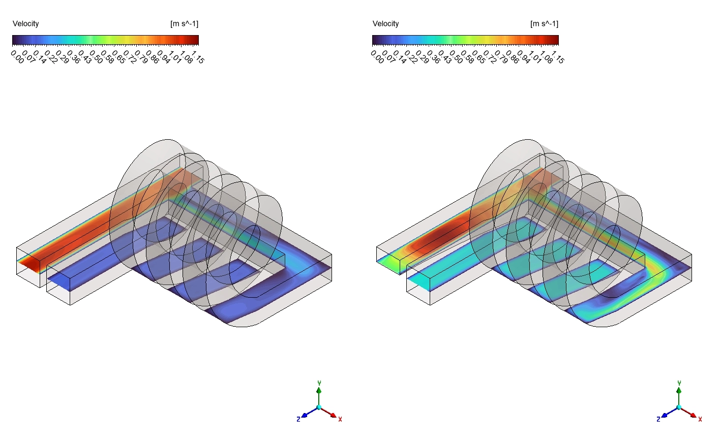
Figure 5: The internal Velocity slices confirming the Adjoint solver successfully breaks the straight jet and feeds the spiral.
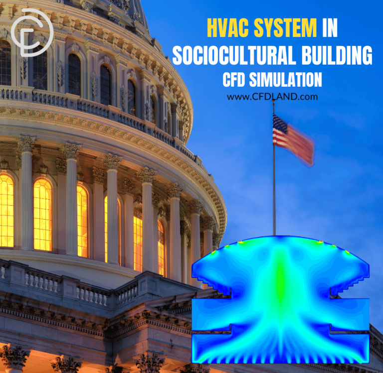
We proceed to analyze the cross-section Pressure contours in the second visual. The legend sets the exact physical limit from 0 to 1.01 [Pa]. The base model on the left displays a uniform dark blue field across all flat sections. The structural Pressure remains near exactly 0 [Pa]. The fluid experiences no opposing forces and simply travels straight forward. The right image reveals the exact mechanical purpose of the new floor ramp created by the Mesh Morpher. As the fluid approaches the morphed incline, the contour transforms into a bright yellow and red zone. This visual data proves the geometric change created a localized high Pressure barrier reaching exactly 1.01 [Pa]. This engineered pressure wall physically blocks the dominant straight path. The moving fluid impacts this exact 1.01 [Pa] barrier and is forced to divert laterally into the secondary helical channel.
The table below reports the exact aerodynamic flow balance data before and after the automated shape optimization process.
| Parameter | Base Model | Optimized Model | Change |
| Helix Outlet Mass Flow Rate | 0.103 | 0.305 | +197 [%] |
| Straight Outlet Mass Flow Rate | 0.897 | 0.695 | -22.5 [%] |
| Helix Flow Split | 10.3 | 30.5 | [%] |
| Straight Flow Split | 89.7 | 69.5 | [%] |
We finalize the analysis by inspecting the internal Velocity slices in the third visual. The base geometry on the left exposes a solid dark red jet occupying the entire straight channel. This massive red zone confirms the fluid retains its maximum momentum near 1.15 [m s^-1] and bypasses the junction entirely. The helical slices remain dark blue, starving the secondary outlet. The morphed geometry on the right shows a massive flow redistribution. The dominant red jet in the straight section vanishes. The color shifts to light blue and green, indicating a severe drop in the forward Velocity. Concurrently, the fluid slices inside the helix shift from dark blue to bright green and orange. The fluid speed increases uniformly throughout the spiral turns. This precise color shift proves the Mesh Morpher successfully broke the dominant straight jet. The fluid mass is now forced evenly through both exit boundaries, achieving the exact design objective.
Frequently Asked Questions (FAQ)
- How does the Mesh Morpher perform shape optimization?
- The Mesh Morpher is a structural tool. You define control points on the solid boundaries. The Optimizer then tests different positions for these points. The morpher stretches and bends the internal grid like rubber to match the new shape. It finds the perfect aerodynamic design without requiring a new grid.
- Why did the base model fail to supply the helix?
- Fluid mass naturally follows the physical path of least mechanical resistance. The straight channel had zero resistance, while the helical branch had high friction. The fluid bypassed the spiral completely because there was no pressure forcing it to turn.
- What physics created the flow diversion in the optimized model?
- The shape optimization raised the main straight floor. This new physical ramp forced the fast fluid to decelerate, creating a localized high Pressure zone of exactly 1.01 [Pa]. This static pressure acts as an invisible fluid wall, pushing the mass into the empty helix.


Reviews
There are no reviews yet.