
In the petroleum industry, long pipelines carry heavy crude oil from the ground. This raw liquid often contains hard solid quartz-sand particles. When this fluid travels at high speeds, the heavy sand hits the metal walls and scrapes away the surface. This dangerous physical damage is called Dynamic Erosion in Oil and Gas Pipes. Over time, the metal loses its thickness and breaks, which causes costly leaks.
Older studies only guess the wear rate on a static, unchanging wall. Our new approach uses Erosion-MDM coupling. This advanced method physically changes the wall shape as the metal wears away. By updating the mesh shape during the run, engineers can see the real grooves forming. This provides true insight into pipeline failure. To understand how engineers manage moving boundaries, visit our Dynamic Mesh Tutorials.
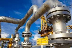
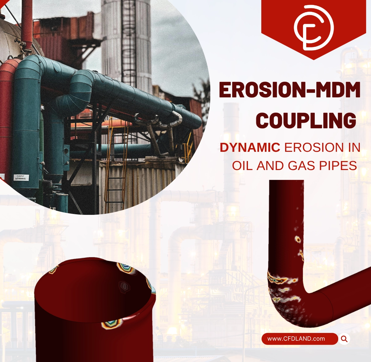
Figure 1: The oil and gas pipes industry relies on costly infrastructure that requires constant protection against internal wear.
Simulation Process: DPM and McLaury Erosion-MDM Setup
To build this study, we created a 3D geometry of a 90-degree elbow pipe. For the fluid physics, we defined crude oil as the continuous liquid phase. Next, we injected the solid quartz-sand as the moving discrete phase. To track the path of every sand grain, the solver uses the Discrete Phase Model (DPM). You can see more particle tracking examples in our DPM category.
The most important physical step is connecting the McLaury erosion equations with the Dynamic Mesh Module (MDM). When a sand particle hits the wall, the solver calculates the tangential and normal forces. Instead of just recording a static number, the Erosion-MDM coupling physically moves the boundary nodes inward. This means the pipe wall actually deforms during the calculation, mimicking real-world metal loss.
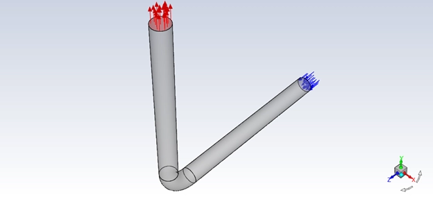
Figure 2: Elbow pipe geometry schematic showing the fluid entry and exit points.
Post-processing: Analyzing 2.20 mm Deformation
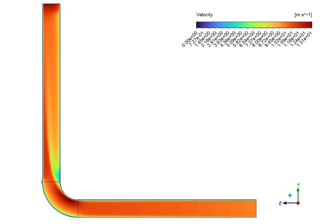
The data perfectly explains the physics of pipeline failure. First, we check the fluid speed using the Velocity contours. In the straight vertical section, the crude oil travels very fast between 11.73 and 13.18 m/s. Here, the flow is safe. The heavy sand moves parallel to the walls, so the damage is very low. The rate remains safely under 0.48 kg/(s·m^2).
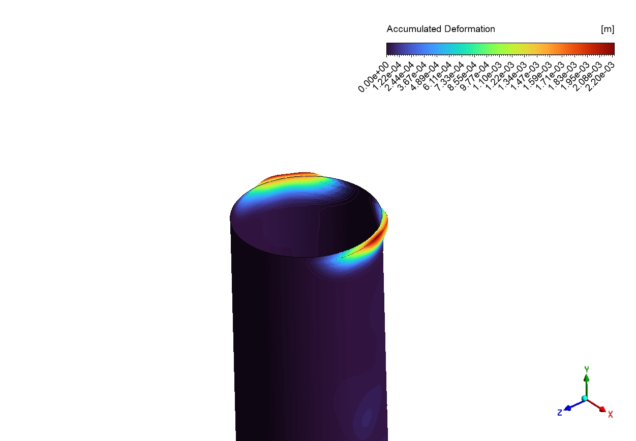
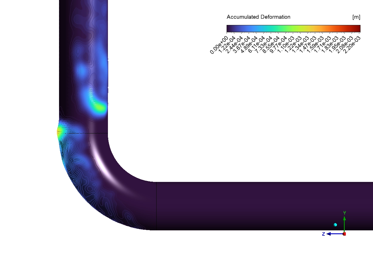
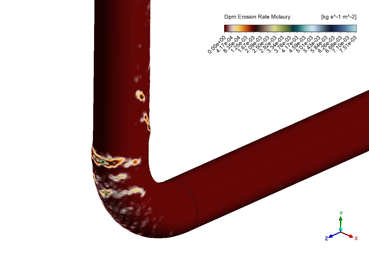
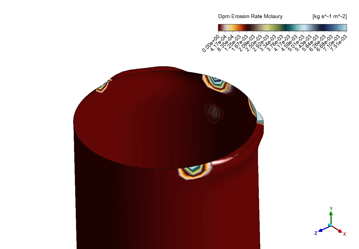
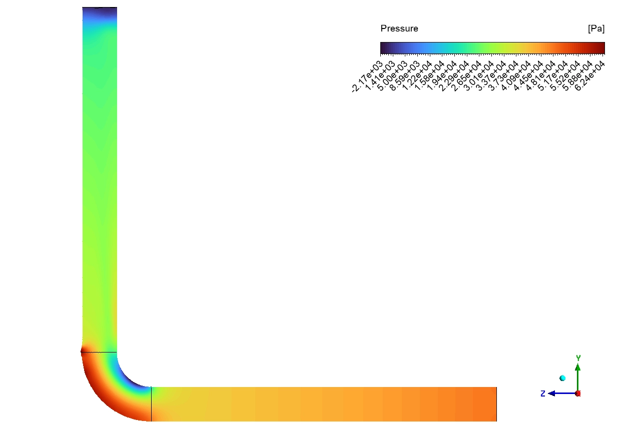
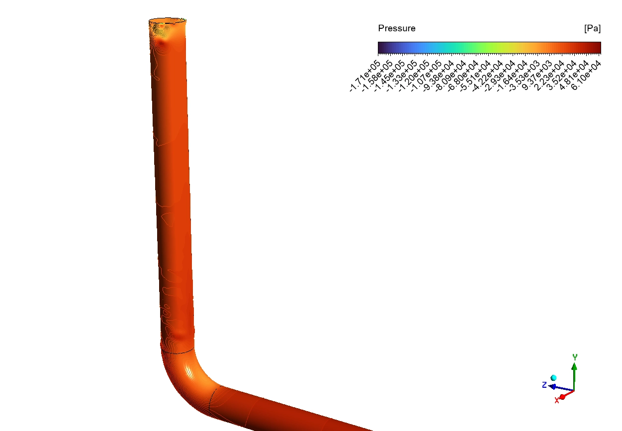
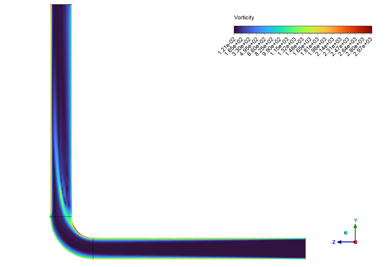
However, the physics change completely at the corner. The liquid oil turns the corner easily, but the heavy sand carries too much physical momentum. The strong centrifugal forces push the sand directly into the outer curve of the elbow. This violent impact creates a dangerous hotspot. The DPM Erosion Rate contours record a vertex maximum erosion rate of 7.51e-3 kg/(s·m^2) at this outer radius. Because we use Erosion-MDM coupling, we can see the true physical result of this impact. The Accumulated Deformation contours show physical grooves cutting deeply into the metal. The hotspot reaches a depth of 0.1 to 2.20 mm. This shape change is critical. When the wall deforms, it disturbs the local fluid flow. This creates a dangerous feedback loop where the changing shape brings more sand to the damaged spot, which accelerates future wear.
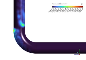
Figure 3: Accumulated Deformation contours from 0.00 to 2.20 mm, visualizing the physical grooves cut into the metal by the Erosion-MDM coupling.
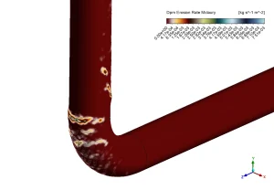
Figure 4: DPM Erosion Rate McLaury contours (0.00-7.61 kg/(s·m²)) mapping the severe concentrated wear hotspots on the pipe wall.
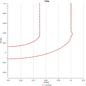
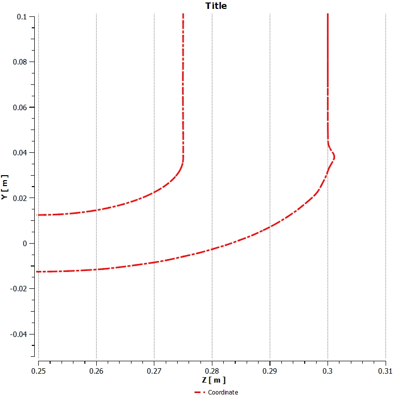
Figure 5: Pipe coordinate plot from ANSYS Fluent dynamic mesh showing elbow centerline geometry (Y vs. Z coordinates): vertical inlet (Z = 0.25-0.28 m straight)
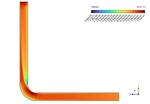
Figure 6: Velocity contours from 0.00 to 13.18 m/s showing the crude oil accelerating heavily through the pipe system.
Frequently Asked Questions (FAQ)
- Why does the most severe damage happen at the elbow outer curve? The fluid turns the corner smoothly, but the solid quartz-sand is heavy. Centrifugal forces push the heavy sand straight forward into the outer metal wall, causing high-impact damage.
- What is the main advantage of Erosion-MDM coupling over older static models? Older models only calculate a static wear rate without changing the pipe. Erosion-MDM coupling physically changes the mesh shape to create real grooves. This shows how the changing geometry affects the ongoing fluid flow and speeds up pipeline failure.
- How deep did the physical wear reach in this specific study? The Accumulated Deformation data proves the sand cut physical grooves measuring 0.1 to 2.20 mm deep at the concentrated outer hotspot.





Reviews
There are no reviews yet.