

Dams and rivers use massive concrete walls called weirs to control water levels and prevent catastrophic flooding. A standard weir is just a straight, flat wall. However, a Labyrinth Weir is cleverly folded into zigzag or triangular shapes. This special Hydraulic Structure makes the physical wall much longer while allowing it to fit perfectly inside the exact same narrow river channel. By folding the concrete wall, the weir can safely pass two to five times more water during heavy rain and dangerous storms. Testing these complex, folded concrete structures with real physical water models costs hundreds of thousands of dollars and takes many months to build. To solve this problem quickly and safely, smart civil engineers use a Labyrinth Weir fluent simulation on a computer. We use the powerful ANSYS Fluent software to create a virtual river and watch exactly how the heavy water and light air mix and move together. By performing a highly accurate CFD Analysis of Labyrinth Weir, designers can perfectly calculate the maximum water discharge capacity without ever pouring a single drop of real concrete. For more easy-to-understand lessons on how to simulate water and air moving together, please explore our Multiphase tutorials.
- Reference [1]: Mattos-Villarroel, Erick Dante, et al. “Hydraulic analysis of a compound weir (triangular-rectangular) simulated with computational fluid dynamics (CFD).” Tecnología y ciencias del agua4 (2021): 112-162.
- Reference [2]: Zounemat-Kermani, Mohammad, Abdollah Ramezani-Charmahineh, and Soudabeh Golestani Kermani. “Studying the relationship between the hydraulic and geometry characteristics of labyrinth weirs based on the historical memory of reported data.” Flow Measurement and Instrumentation82 (2021): 102079.
- Reference [3]: Mattos-Villarroel, Erick Dante, et al. “Methodological proposal for the hydraulic design of labyrinth weirs.” Water4 (2023): 722.
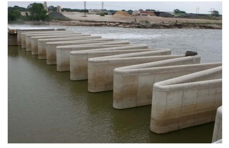
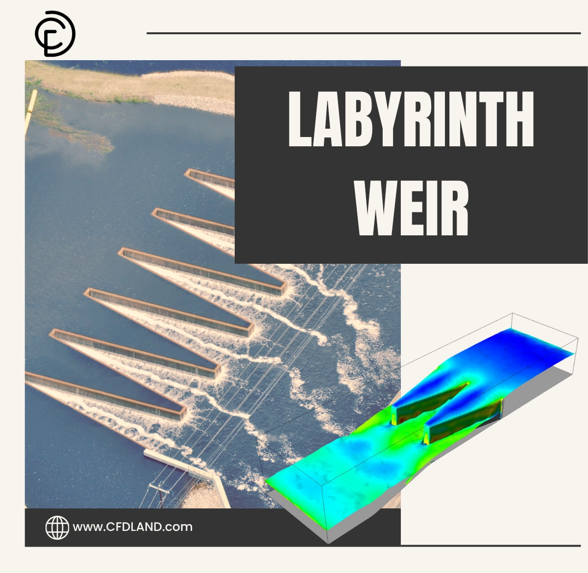
Figure 1: Real Labyrinth big scale, showing the physical folded zigzag geometry of a massive concrete hydraulic structure designed to maximize water discharge.
Simulation Process: VOF Multiphase and Transient Setup
For this Labyrinth Weir ANSYS Fluent project, we built a complete 3D computer model of the folded zigzag wall sitting inside an open water channel. To ensure the computer calculates the complex water physics perfectly, we divided this empty 3D space into a very clean, high-quality grid containing exactly 221,411 unstructured polyhedral cells. We purposefully made these tiny cells extremely small near the top of the wall and near the water surface so the software could accurately catch the thin layer of flowing water bending over the complex concrete geometry.
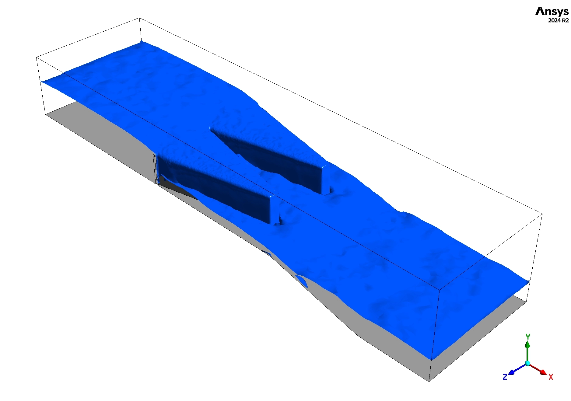
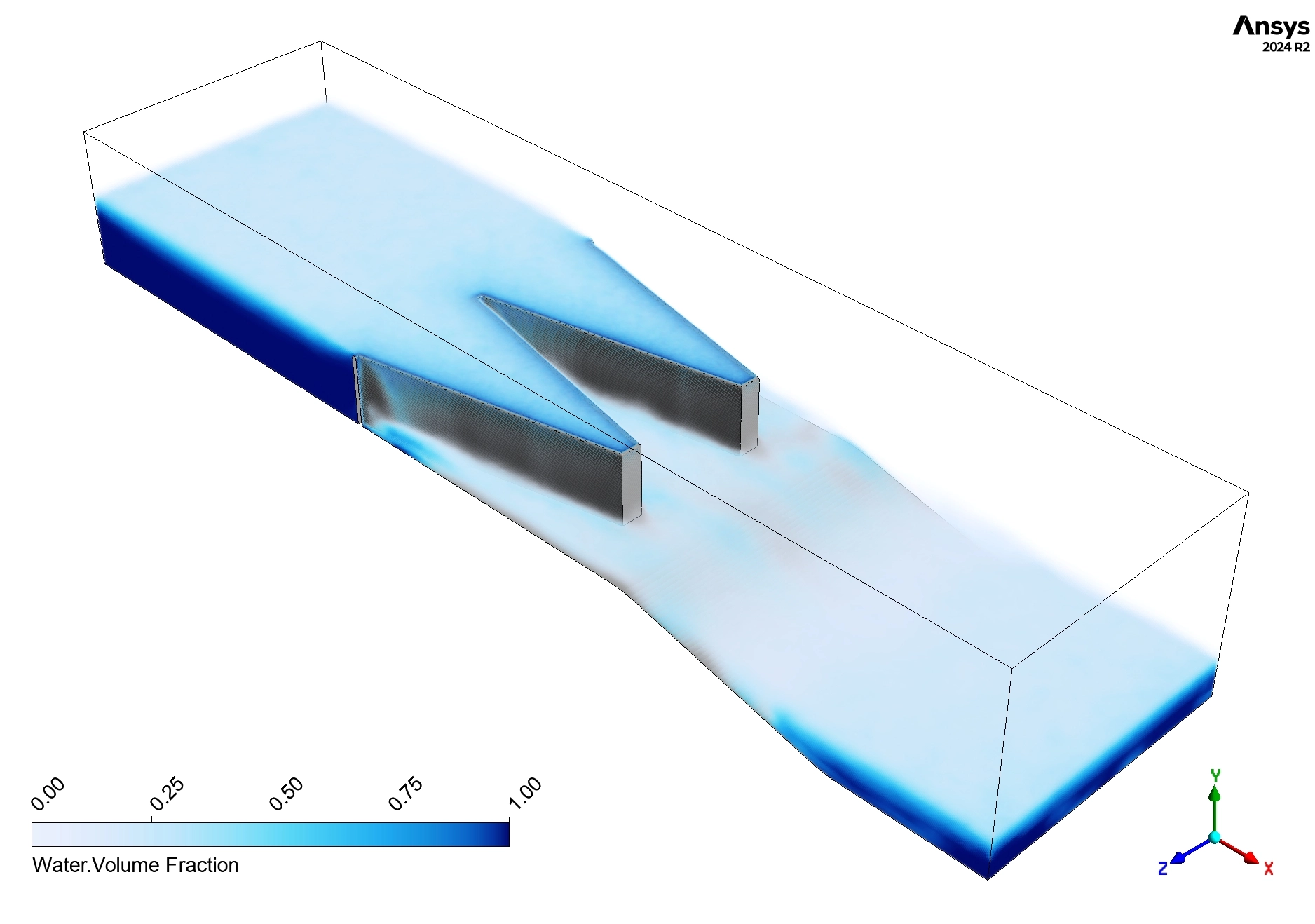
We set up the physics using the Volume of Fluid (VOF) + Open channel Flow multiphase model in ANSYS Fluent. This brilliant mathematical tool tracks the exact free surface boundary line where the heavy liquid water meets the invisible light air above it. We also activated wall adhesion rules to simulate how natural surface tension makes the water stick to or peel away from the concrete walls. Finally, the Labyrinth Weir fluent solver was set to run a transient, time-dependent calculation. This allowed the computer to watch the water flow grow from a calm, quiet river into a steady, powerful, and continuous waterfall crashing over the folded crest.
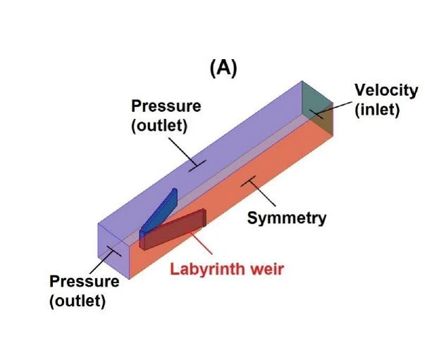
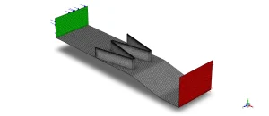
Figure 2: Schematic of domain and poly mesh, displaying the 3D computer space and the high-quality unstructured polyhedral grid (221,411 cells) used for the calculation.
Post-processing: Deep Analytical Review of Hydrodynamic Performance and Flow Separation
To truly master this Labyrinth Weir fluent simulation study, we must strictly analyze the visual data without taking any shortcuts. The survival of a dam depends entirely on how the water accelerates, where it gets trapped, and how its destructive energy is managed downstream. We will first examine the extreme acceleration caused by the folded walls, analyze the dangerous swirling zones, and visually prove how the energy is safely destroyed at the bottom of the waterfall.
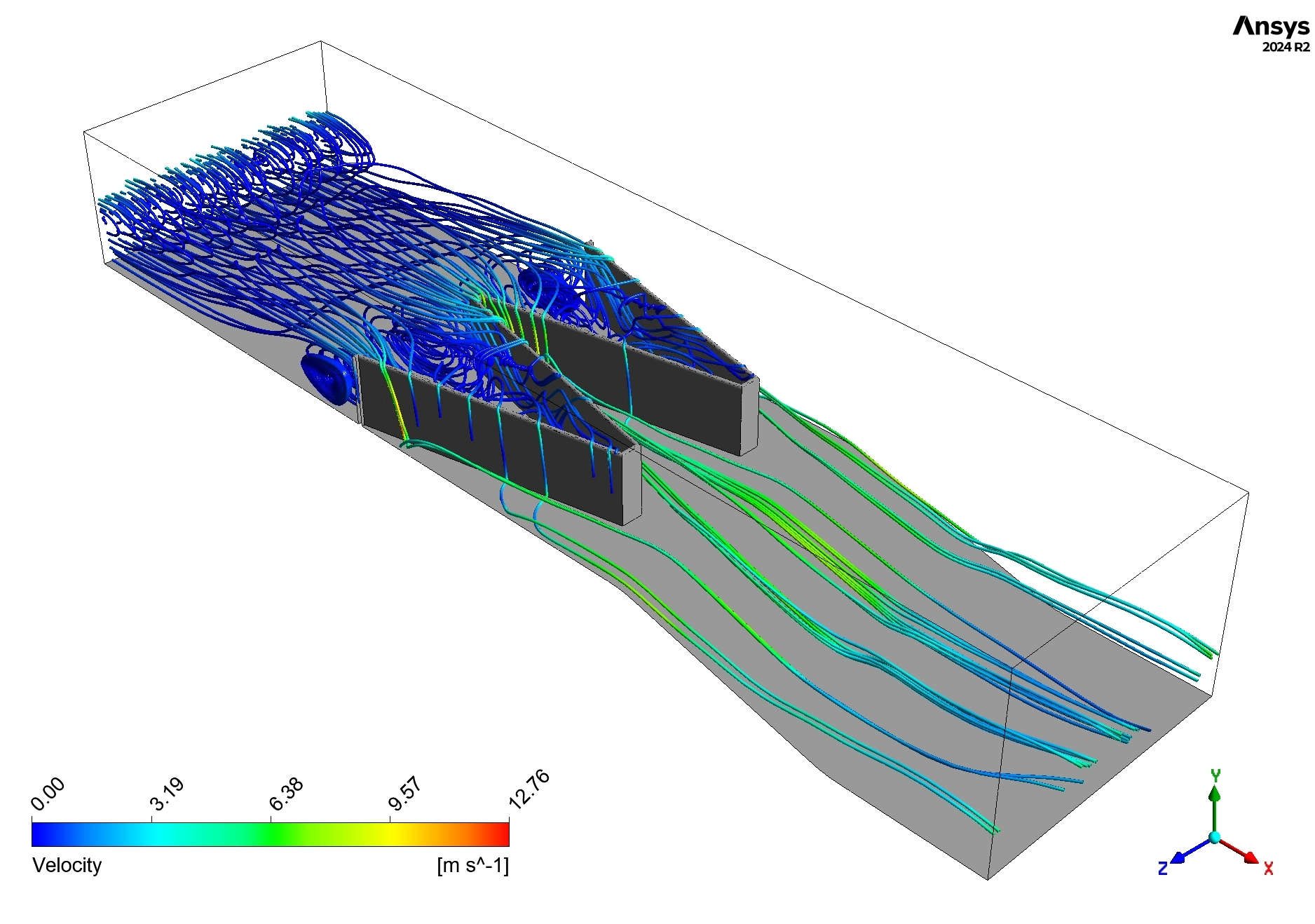
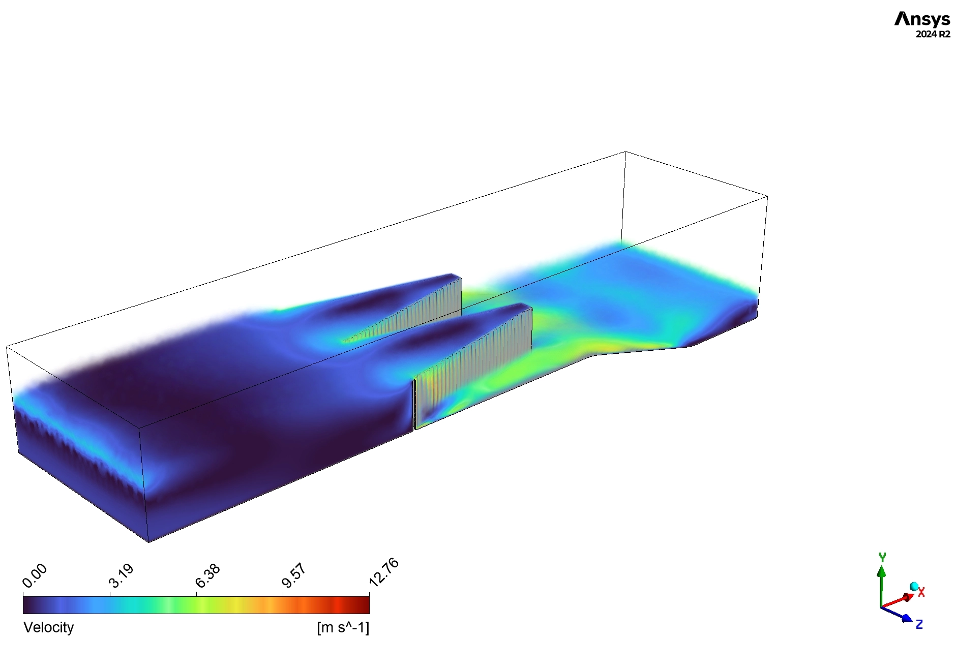
The 3D Velocity Streamlines (Figure 4) reveal the incredible power of the zigzag geometry. Far upstream, the river water approaches the weir slowly and safely, displaying dark blue colors that indicate a calm speed of 0 to 2.19 m/s. However, as the massive volume of water is squeezed into the narrow folded cycles of the concrete wall, it is forced to speed up incredibly fast. The streamlines rapidly change to bright cyan and green, proving that the water reaches a massive peak speed of 12 to 12.76 m/s the exact moment it falls over the crest. This extreme acceleration proves visually that the labyrinth shape successfully sucks massive amounts of water out of the river to prevent upstream flooding.

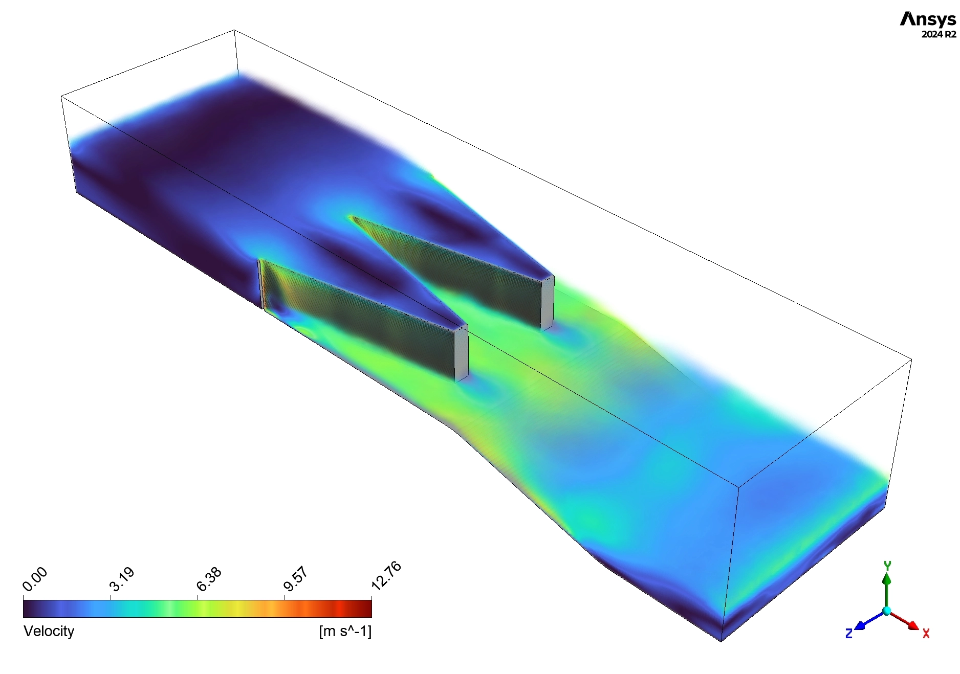
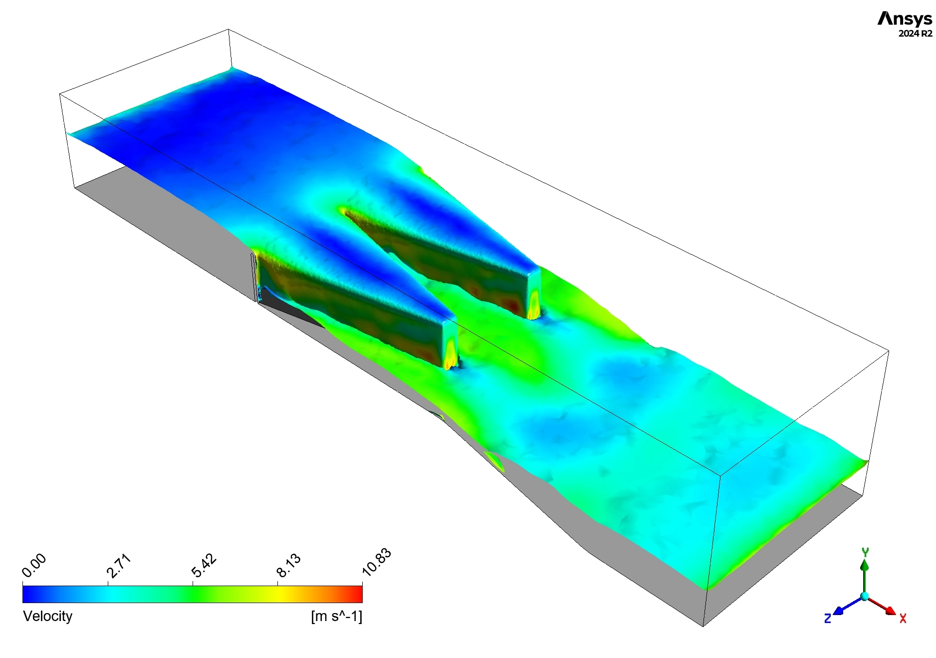
Figure 3: Free surface velocity contour on labyrinth weir from VOF CFD, visualizing the slow upstream water accelerating into a high-speed waterfall (nappe) over the crest, followed by a turbulent hydraulic jump downstream.
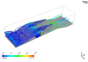
Figure 4: Velocity streamlines in labyrinth weir open channel flow from CFD simulation, illustrating the extreme water acceleration up to 12.76 m/s and the swirling recirculation zones trapped inside the sharp corners.
However, the streamlines also reveal a critical hidden danger known as flow separation. By looking closely at the sharp corners of the zigzag sidewalls and the area directly behind the concrete structure, we can see swirling blue lines. This visual data clearly proves that water gets trapped and violently spins in circles in these corners. This spinning, trapped water eats up the river’s forward energy and causes unwanted, chaotic pressure changes against the concrete. By seeing the exact locations of these swirling recirculation zones in this CFD Analysis of Labyrinth Weir, structural designers can go back into the software, smooth out the sharp angles of the walls, and eliminate the trapped water to make the weir flow perfectly smoothly.
Finally, we must evaluate the downstream safety by looking at the Free Surface Velocity Contour (Figure 3). As the water shoots over the wall, it creates a waterfall known as a nappe. The contour shows this nappe glows green and orange, carrying a high velocity of 5.42 to 10.83 m/s. Because the bright green colors are not perfectly identical in every single fold, it scientifically proves the discharge is non-uniform, meaning some sections of the wall carry a much heavier, more dangerous burden of water than others. Once the water hits the bottom, it slows down dramatically to between 2.71 and 5.42 m/s. The messy, irregular blue and cyan color patterns on the bottom surface perfectly visualize a “hydraulic jump.” This chaotic jump happens when the fast, heavy falling water crashes violently into the slow, deep tailwater below it. This massive crash creates huge turbulence that successfully destroys the water’s destructive kinetic energy. Because this highly accurate simulation reveals exact local speeds over 10 m/s near the crest and heavy crashing downstream, civil engineers know exactly where to pour thicker, reinforced concrete and where to place heavy protective rocks, guaranteeing the dam survives massive floods without breaking.
Key Takeaways & FAQ
- Q: What is a Labyrinth Weir?
- A: It is a special dam wall folded into a zigzag or triangular shape. This folding makes the wall much longer than a straight line, allowing it to safely discharge massive amounts of floodwater without taking up more space in the river.
- Q: Why do we use the VOF multiphase model in ANSYS Fluent?
- A: The Volume of Fluid (VOF) model is a mathematical tool that perfectly tracks the exact boundary (the free surface) between the heavy liquid river water and the invisible light air resting above it.
- Q: What does the hydraulic jump in the velocity contour tell us?
- A: The hydraulic jump shows exactly where the fast falling water crashes into the slow downstream water. This crash destroys the destructive energy of the water, telling engineers exactly where to place heavy rocks (riprap) to prevent the riverbed from washing away.


Reviews
There are no reviews yet.