
![The 2D Pressure contour showing a massive dark blue suction zone on the morphed wing, dropping toward -465.15 [Pa].](https://cfdland.com/wp-content/uploads/2026/06/p-3.webp)

![2D Velocity contour proving the optimized wing accelerates air smoothly over the top surface to reach 32.92 [m s^-1].](https://cfdland.com/wp-content/uploads/2026/06/v-6.webp)
![2D Velocity contour proving the optimized wing accelerates air smoothly over the top surface to reach 32.92 [m s^-1].](https://cfdland.com/wp-content/uploads/2026/06/v2-4.webp)
Flight efficiency is critical in modern aviation engineering. Designers must constantly increase the upward lifting force while decreasing the backward drag force. This delicate ratio controls the fuel consumption and the overall flight stability. Standard symmetrical wing shapes often require physical modifications to reach strict performance goals. In the past, engineers relied on expensive physical wind tunnel models to test new geometric shapes. Today, computational shape optimization provides a perfectly precise mathematical solution.
The adjoint solver is an advanced algorithm that calculates the exact fluid sensitivity along the solid boundary. It observes the physical forces and automatically deforms the wing shape to achieve the absolute best aerodynamic performance. Engineers who study professional aerodynamics and aerospace tutorials recognize the massive value of these automated mathematical tools. In this technical analysis, we investigate the classic NACA 0010 airfoil operating at an angle of attack of exactly 2.85°. We will examine exactly how the intelligent software alters the physical metal structure to dramatically increase the lift-to-drag ratio.
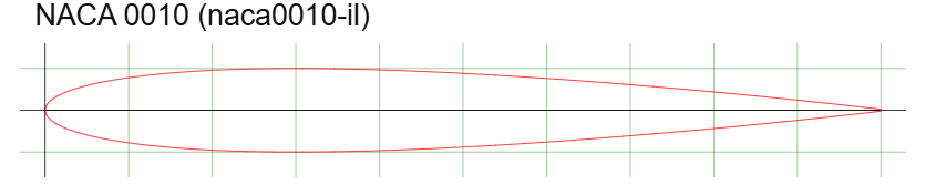
Figure 1: NACA 0010 profile section
Simulation Process: Mathematical Shape Deformation
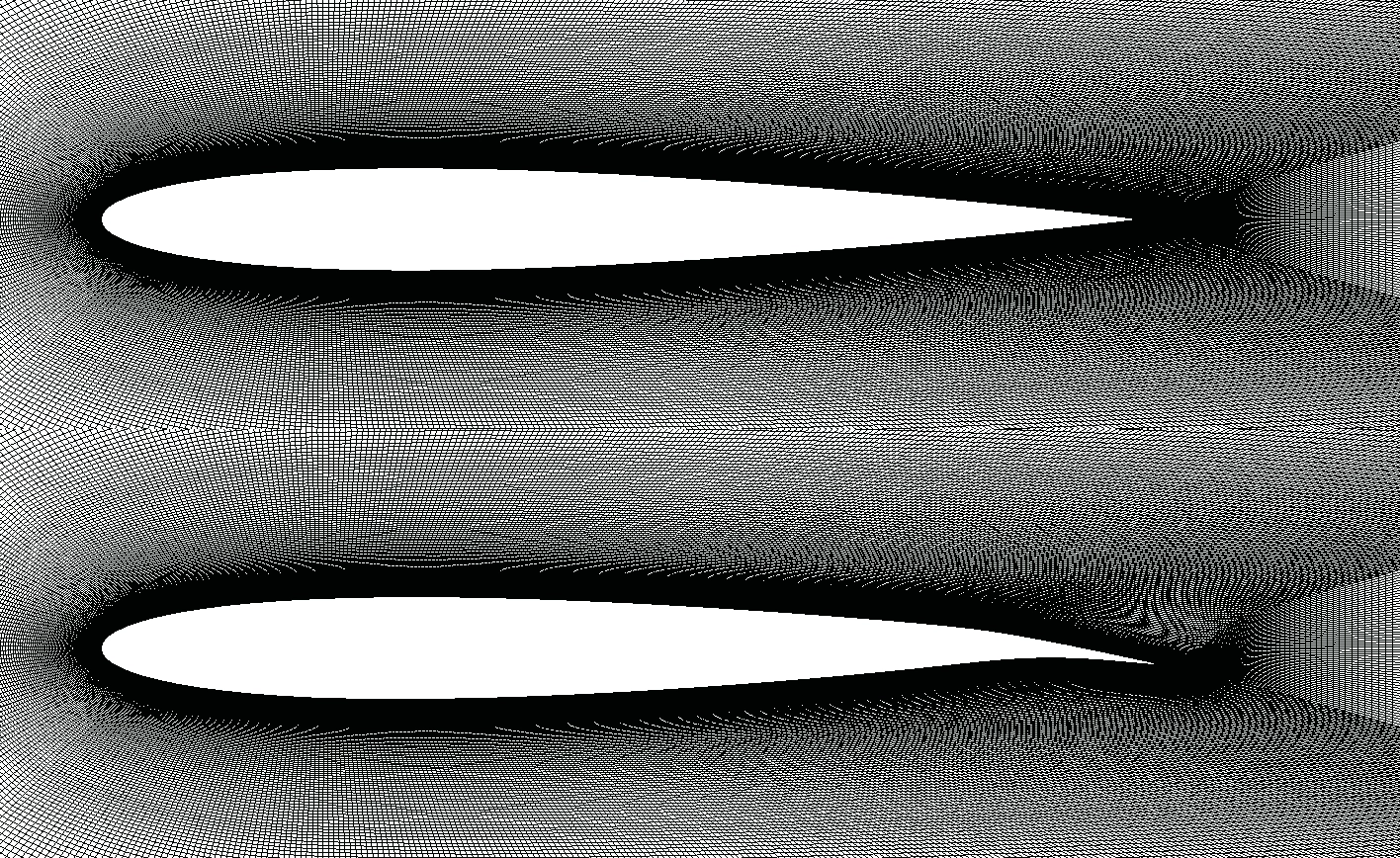
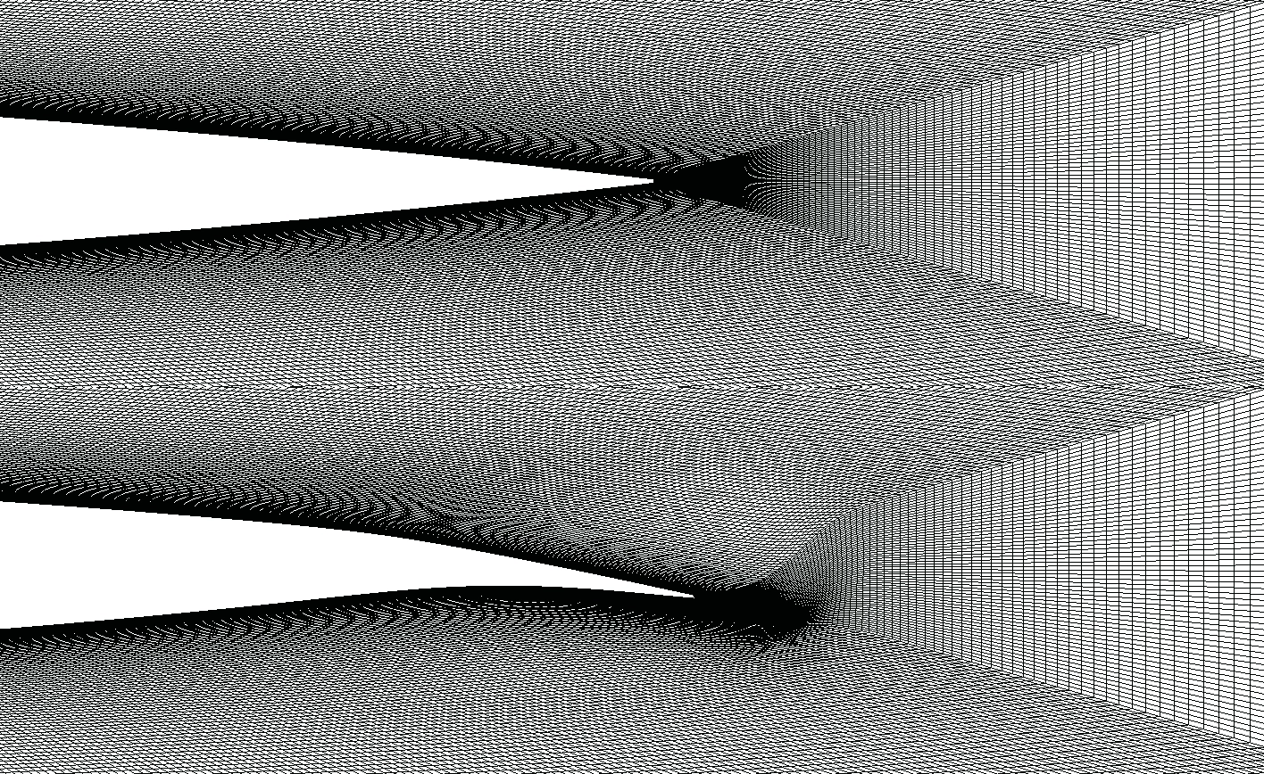
We establish the numerical simulation by constructing a wide C-shape domain around the two-dimensional NACA 0010 airfoil. We generate a fully-structured grid using ICEM software to guarantee high mathematical accuracy near the solid walls. The fluid enters the domain with a constant momentum, and the solid airfoil maintains a fixed angle of attack of exactly 2.85°.
To improve the physical flight performance, we deploy the adjoint solver algorithm within ANSYS Fluent. We assign a strict mathematical objective to the software. We instruct the computer to maximize the total lift-to-drag ratio. The solver calculates the exact sensitivity of the surface forces. It uses this pure mathematical data to morph the structured grid. The software stretches and bends the solid boundary smoothly without adding or removing any grid elements until it reaches the optimal aerodynamic geometry.
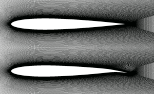
Figure 2: Structured grid generated over the basic airfoil and optimized one via ICEM
Post-processing: Physics of Flow Redirection and Lift Generation
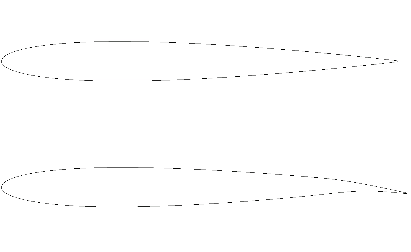
We will analyze the visual data to understand the exact physical changes. We compare the original base model to the optimized model. We study the geometric shape, the structural pressure, and the fluid speed based strictly on the provided graphics. First, we examine the geometric shape comparison. The top profile is the original symmetric NACA 0010 airfoil. The bottom profile is the new optimized shape. We can clearly observe there is absolutely no change in the front leading edge. The front remains thick and rounded. However, a major geometric transformation occurs at the back. The trailing edge now bends significantly downward. The Adjoint solver calculated that bending the trailing edge directly controls the air direction. This bent tail keeps the air attached to the metal longer and smoothly reduces the backward drag force.
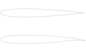
Figure 3: cross section before and after optimization via Adjoint solver
The table below summarizes the exact changes observed during the optimization process.
| Parameter | Before Optimization | After Optimization | Change |
| Lift-to-Drag Ratio | 29.38 | 54.94 | +87.0% |
Next, we study the Pressure contours. The legend defines the physical pressure limits from exactly -465.15 to 244.15 [Pa]. The base model on the top displays a light green color on both the upper and lower surfaces. Because the pressure is mostly equal on both sides, the wing produces very low lift. The optimized model on the bottom shows a radical physical transformation. A massive dark blue zone forms over the entire top surface. This dark blue color indicates a severe drop in pressure. This creates a powerful aerodynamic suction. The wing is pulled powerfully upward, which generates massive lift. We verify this physical change by reading the Pressure versus X data chart in the third image. The horizontal line represents the length of the wing. The vertical line represents the pressure force. The black squares show the original wing. The gap between the top and bottom black curves is very small. The red squares show the optimized wing. The Adjoint solver expanded this gap massively. The lower red curve drops extremely deep, reaching past -400 [Pa]. This massive red area proves mathematically that the bent trailing edge successfully multiplied the total lifting force without changing the leading edge.
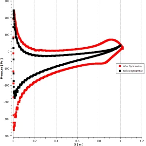
Figure 4: pressure vs. X graph
![The 2D Pressure contour showing a massive dark blue suction zone on the morphed wing, dropping toward -465.15 [Pa].](https://cfdland.com/wp-content/uploads/2026/06/p-3-300x184.webp)
Figure 5: The 2D Pressure contour showing a massive dark blue suction zone on the morphed wing, dropping toward -465.15 [Pa].
![2D Velocity contour proving the optimized wing accelerates air smoothly over the top surface to reach 32.92 [m s^-1].](https://cfdland.com/wp-content/uploads/2026/06/v-6-300x184.webp)
Figure 6: 2D Velocity contour proving the optimized wing accelerates air smoothly over the top surface to reach 32.92 [m s^-1].
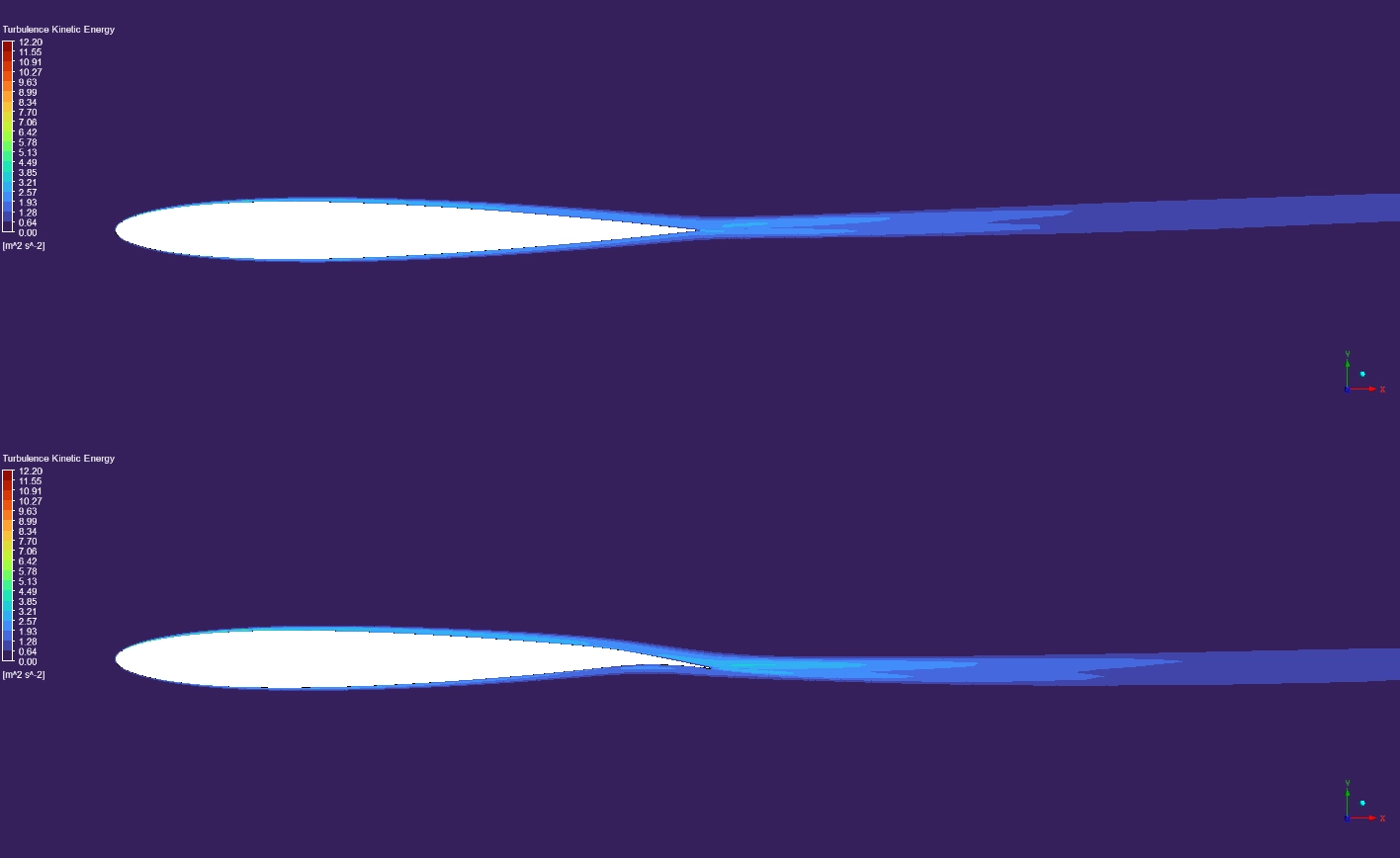
Finally, we observe the Velocity contours. The legend shows the air speed ranging from exactly 0.00 to 32.92 [m s^-1]. In the optimized model on the bottom, a bright orange and red zone appears above the wing. The air accelerates rapidly to the maximum limit of exactly 32.92 [m s^-1]. In fluid physics, high velocity directly creates the low pressure suction we saw earlier. Notice the green wake trail behind the wing. Because the trailing edge is bent downward, the air leaves the wing very smoothly. This smooth exit reduces the chaotic messy air in the wake. A clean wake proves the new trailing edge design successfully lowers the total aerodynamic drag.
Frequently Asked Questions (FAQ)
- Why did the Adjoint solver only bend the trailing edge?
- The base rounded leading edge was already efficient for slicing the air at this specific angle. The main aerodynamic failure was at the back of the wing. By bending the trailing edge down, the solver forces the air to leave the metal smoothly, which instantly improves the lift.
- What is a structured grid in the ICEM software?
- To calculate air flow accurately, engineers cut the virtual space into tiny geometric boxes. A structured grid uses perfectly ordered, straight boxes instead of random triangles. These perfect boxes calculate the delicate air friction on the solid wing surface flawlessly.


Reviews
There are no reviews yet.