


Airplanes fly because of the special shape of their wings. One popular shape for small planes and drones is the NACA E205 Airfoil. This shape is curved on the top and flat on the bottom. It is designed to help planes lift off the ground easily. However, building and testing real wings in a wind tunnel is very expensive. To save money, engineers use NACA E205 Airfoil CFD simulation. This allows us to test the wing on a computer.
This project is a NACA E205 Airfoil fluent tutorial. We will teach you how to simulate the wind flowing over the wing. We use ANSYS Fluent to solve complex math equations and visualize the air pressure. By performing this 2D airfoil Fluent analysis, we can predict if the plane will fly safely or fall. For more lessons on airflow physics, please explore our Fluid Mechanics tutorials.
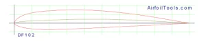
Figure 1: Schematic of NACA E205 Geometry, showing the specific curvature of the upper and lower surfaces designed for general aviation aircraft.
Simulation Process: Structured Meshing and Solver Setup
To start this NACA E205 Airfoil ANSYS fluent analysis, we modeled the 2D cross-section of the wing. The most critical part of the setup is the Mesh (the grid). We created a high-quality Structured Mesh using a C-grid shape. This mesh contains exactly 130,200 cells. We made the cells very small and tight near the wing walls. This is necessary to calculate the friction of the air rubbing against the surface.
We configured the ANSYS Fluent solver for a high-stress test. We set the Angle of Attack to 20°. This is a very steep angle. At this angle, wings often stop generating lift and start to Stall. The computer calculated the Lift and Drag Forces by solving the flow equations across the domain. This setup allows us to see exactly how the NACA E205 Airfoil fluent simulation behaves under dangerous conditions.

Figure 2: Structured Grid Generation, displaying the C-grid topology with 130,200 hexahedral cells concentrated near the leading and trailing edges to capture the airflow accurately.
Post-processing: Analysis of Aerodynamic Stall
To truly understand the physics of this NACA E205 Airfoil CFD simulation, we must tell the story of the air particle. The story begins at the front of the wing, known as the leading edge. The incoming air (Figure 3) approaches at about 7 to 8 m/s. When it hits the curved nose of the airfoil, it is forced to speed up. The Velocity Contours show a bright Red/Orange zone on the top surface. Here, the air reaches a maximum speed of 9.91 m/s. According to Bernoulli’s principle, this fast air creates low pressure, which pulls the wing up. This is how lift is generated.
However, the story changes as the air moves further back. Because the Angle of Attack is 20°, the hill the air must climb is too steep. The air cannot hold onto the surface. At about 60% to 70% of the way down the wing, the flow breaks away. This is called Flow Separation. Behind the wing, you can see a large Blue Zone. This is a “Wake” or recirculation zone where the air is moving very slowly (0 to 5 m/s) and swirling around. This chaotic dead air destroys the smooth lifting force.
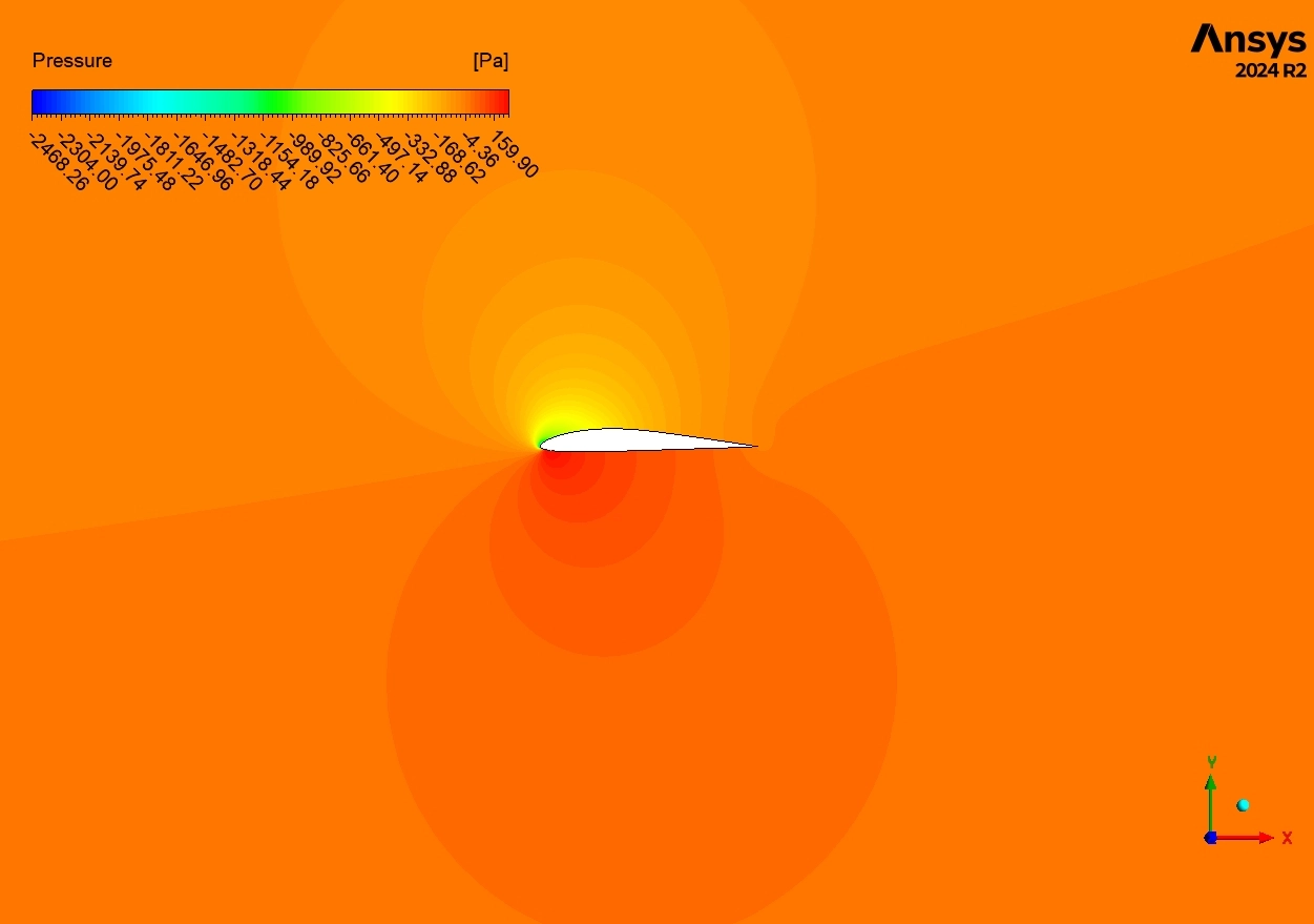
The numerical data confirms this “Stall” event. The simulation calculated a Lift Force of 3509.2 N. This results in a Lift Coefficient (Cl) of 0.705. For a healthy wing, this number should be much higher (usually over 1.2). The low Cl proves the wing is losing power. Furthermore, the Drag Coefficient (Cd) is 0.038. While this seems small, the report notes that 98.9% of this is Pressure Drag. This means the drag is not caused by friction (air rubbing the skin), but by the suction of that large Blue Wake pulling the wing backward. This NACA E205 Airfoil fluent simulation successfully predicts that flying at a 20° angle is unsafe.
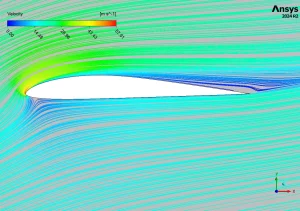
Figure 3: Velocity Streamlines Contours, visualizing the airflow acceleration over the upper surface (Red) and the large flow separation zone (Blue) behind the airfoil at a 20-degree angle of attack.
Key Takeaways & FAQ
- Q: What happens at a 20° Angle of Attack?
- A: The wing experiences “Stall.” The airflow separates from the surface, creating a large wake and reducing lift in this NACA E205 Airfoil CFD simulation.
- Q: Why is the Lift Coefficient only 0.705?
- A: Because of the flow separation. A normal flying wing would have a higher coefficient, but the steep angle destroys the lift.
- Q: What is Pressure Drag?
- A: It is the resistance caused by the difference in pressure between the front and back of the wing. In this NACA E205 Airfoil ANSYS fluent case, it makes up 98.9% of the total drag.


Reviews
There are no reviews yet.