


Modern engineering uses very tiny metal tubes, known as microcombustors, to burn a clean mixture of hydrogen fuel and air. This exact process is highly important for building small, portable micro-power systems, such as thermophotovoltaic cells. Because hydrogen fuel holds a massive amount of energy, it is a perfect fuel source. However, designing these tiny power machines is very difficult. Inside a small tube, the hot fire sits very close to the cold metal walls. The biggest mechanical problem in these tiny tubes is that the cold walls steal too much heat from the fire. This massive heat loss can completely stop the burning process, causing a dangerous failure called flame quenching. To stop this from happening, smart engineers perform a highly accurate Premixed H2-Air Combustion CFD Simulation. This advanced computational representation safely tests the exact fire temperature and gas expansion without building expensive metal prototypes. By studying this specific tutorial project, designers can clearly see exactly how the invisible fuel burns. To learn more about how software calculates hot fire and complex chemical mixing, please explore our professional Combustion tutorials category. A detailed CFD analysis helps manufacturers change the tube shape to keep the flame perfectly stable and maximize the final electricity output.
- Reference: Li, Jun, et al. “Fundamental flame characteristics of premixed H2–air combustion in a planar porous micro-combustor.” Chemical engineering journal283 (2016): 1187-1196.
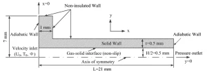
Figure 1: Illustration of the planar micro-combustor, showing the basic metal shape and flow direction.
Simulation Process: 2D Axisymmetric Meshing and Species Transport Setup
For this high-temperature thermal project, we created a highly precise geometry of a tiny microcombustor tube. To make the software run much faster without losing any mathematical accuracy, we used a smart 2D axisymmetric method instead of drawing a full 3D cylinder. We carefully divided this 2D space into a highly structured grid made of exactly 7056 cells to help the fluid solver calculate the flow perfectly.
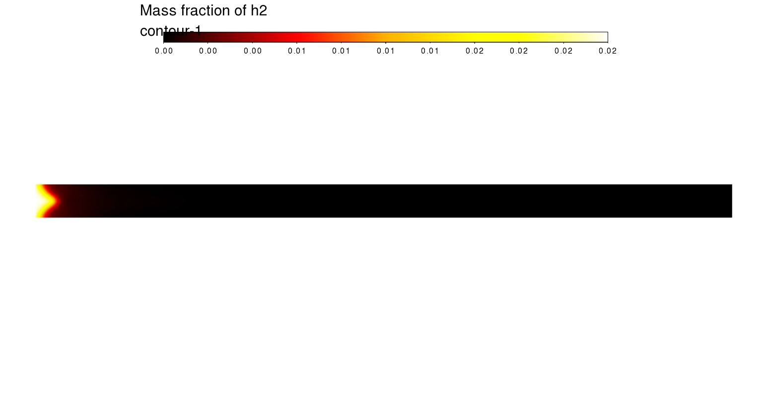
Inside the ANSYS Fluent software, we activated the professional Species Transport module. This smart module strictly tracks all the different chemical gases, such as hydrogen (H2), oxygen (O2), nitrogen (N2), water vapor (H2O), and OH radicals. Next, we applied a special Premixed Combustion model at the tube inlet to define the perfect mixture of fuel and air entering the machine. The core mathematical brain of this CFD simulation is a detailed finite-rate chemistry model containing exactly 19 chemical reactions. This complex setup allows the software to correctly calculate every single chemical change.
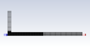
Figure 2: Structured grid on the domain, highlighting the highly precise mesh containing exactly 7056 cells.
Post-processing: Analysis of Flame Stability and Heat Loss
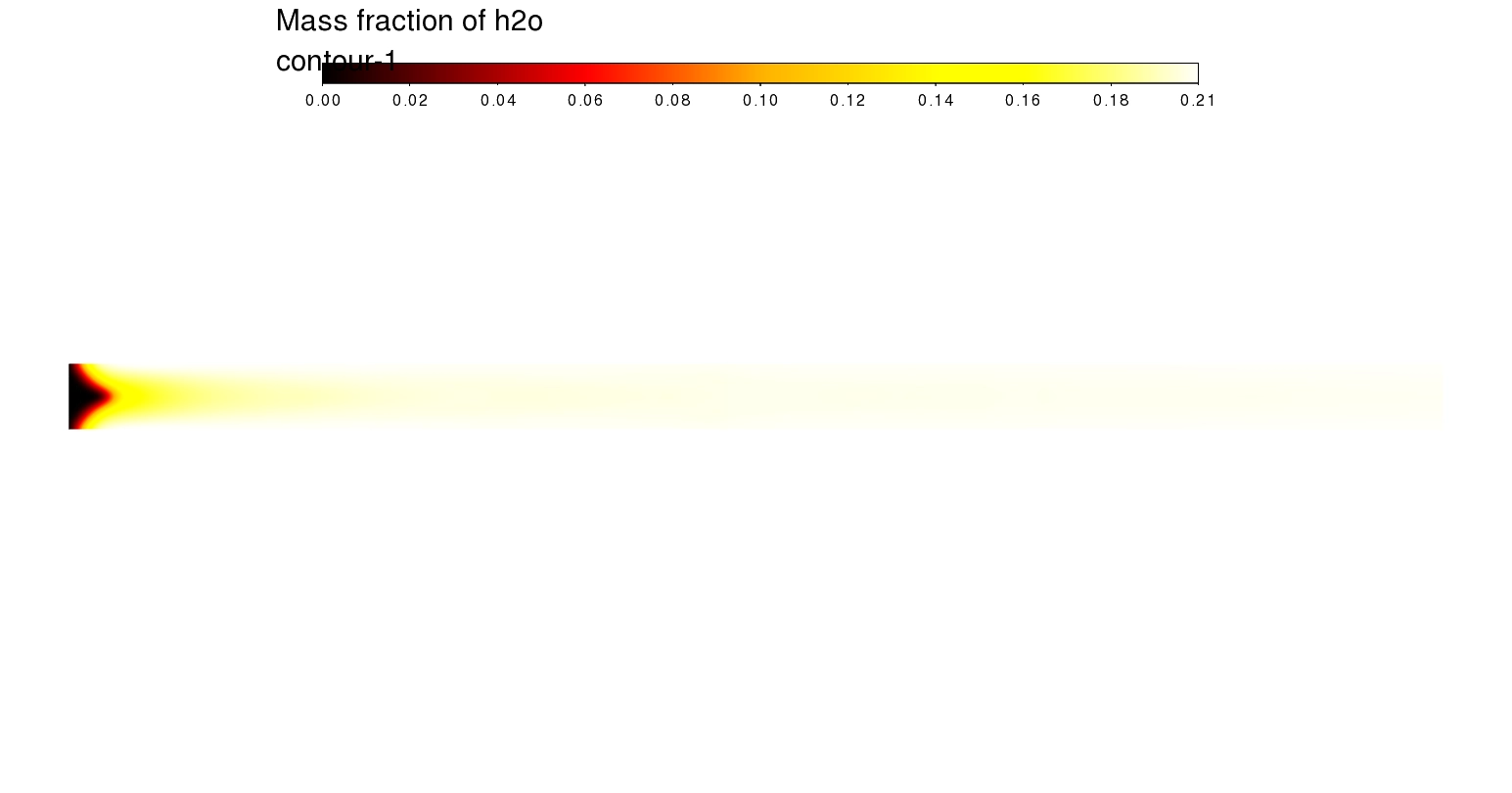
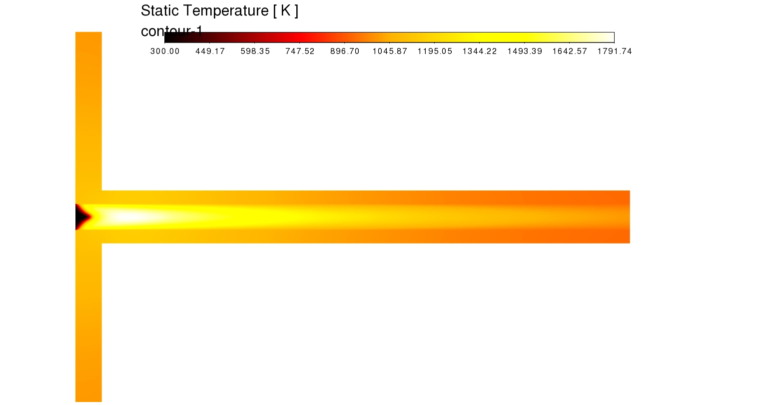
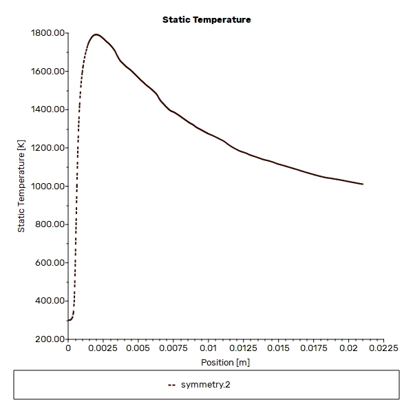
Let us deeply and carefully analyze the exact simulation contours to explain the combustion performance to micro-power manufacturers. First, we examine the Static Temperature contour and the exact centerline data. The visual data mathematically proves that a stable flame successfully anchors very close to the inlet. This anchoring happens at a very short distance of exactly x ≈ 0.0025 m. At this exact spot, the premixed gas ignites and creates a massive peak temperature of exactly 1791.74 K (roughly 1800 K), showing a bright white and yellow color. However, as the hot gas travels down the tube, the temperature drops significantly from 1800 K down to about 1000 K at the exit. This huge 800 K temperature drop is a massive engineering warning. It perfectly proves the critical problem of heat loss. The hot combustion gases continuously lose their thermal energy to the cooler steel walls. By seeing this exact heat loss, manufacturers know they must use a different insulating material to stop the flame from dying.
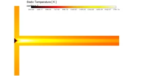
Figure 3: Static Temperature contour (up to 1791.74 K), showing the white hot flame core and the dark temperature decay due to heat loss to the steel walls.
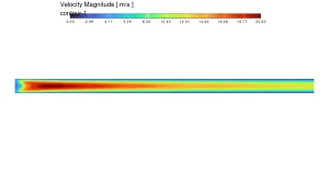
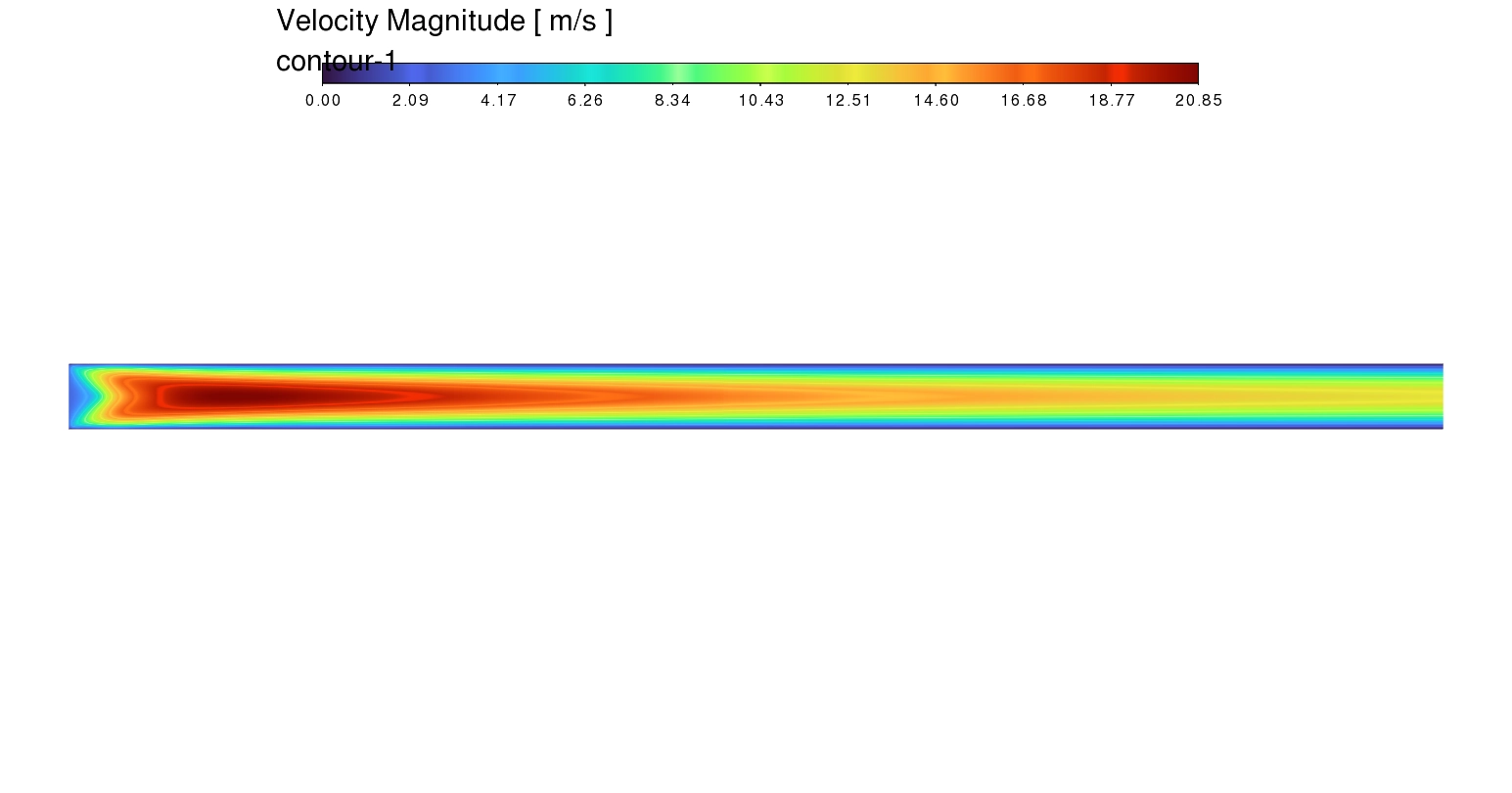
Figure 4: Velocity Magnitude contour (0 to 20.85 m/s), illustrating the strong flow acceleration at the centerline caused by extreme gas expansion.
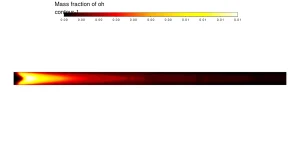
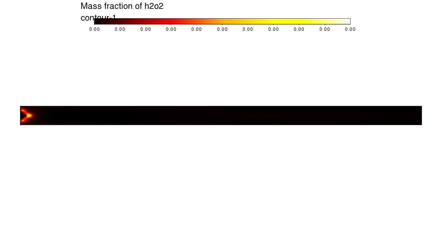
Figure 5: OH Mass Fraction contour, clearly identifying the exact thin flame front location using the high concentration of hot radical gases.
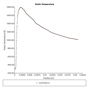
Figure 6: Plot of Static Temperature along the centerline, quantifying the sharp temperature rise at x ≈ 0.0025 m and the heavy 800 K decay drop.
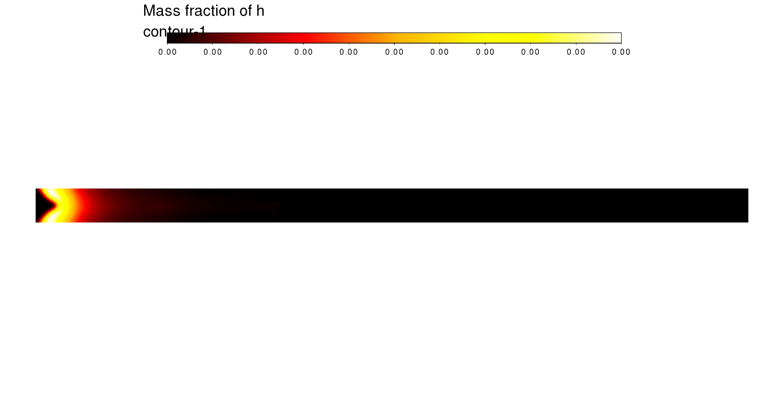
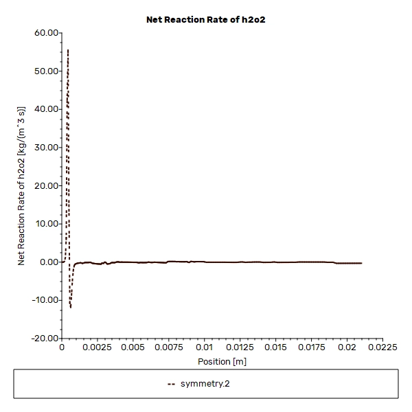
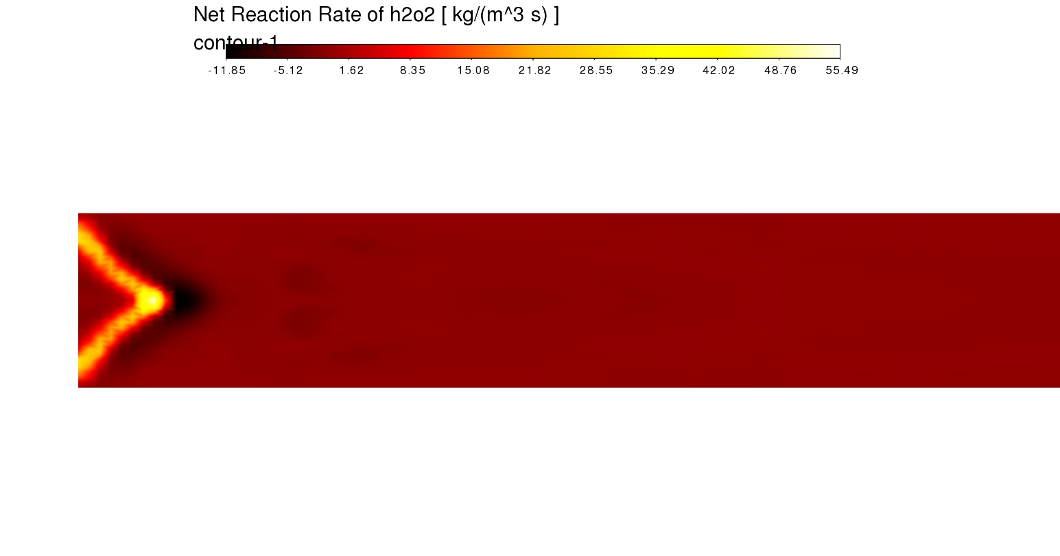
Next, we evaluate the exact Chemical Radicals and Reaction Rates. The Mass fraction of OH contour highlights a very bright, thin shape. Because OH radicals only exist in the hottest parts of a fire, this contour precisely maps the exact flame front location. Furthermore, the Net Reaction Rate of H2O2 plot confirms this by showing a sharp, massive chemical spike right at the start. This exact data mathematically proves that 100% of the major chemical burning happens in a tiny, thin region near the inlet, rather than spreading slowly across the whole tube.
Finally, we study the Velocity Magnitude contour to measure the gas power. The contour shows a dark red center where the gas speed shoots up to an extreme maximum of 20.85 m/s. This high speed happens because the intense 1800 K heat forces the gas to rapidly expand and push forward. This strong thermal acceleration is the exact driving force needed for micro-power systems. By using this exact data, a smart designer can correctly harvest this 20.85 m/s kinetic energy to generate the highest possible electricity for their thermophotovoltaic cells.
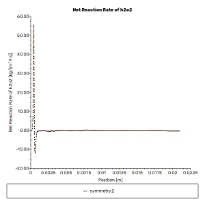
Figure 7: Plot of the Net Reaction Rate of H2O2, mathematically proving the location of the thin region where all major chemical reactions occur.
Frequently Asked Questions (FAQ)
- What is flame quenching in a microcombustor?
- Flame quenching is a dangerous problem where the fire completely stops burning. It happens in very small tubes because the cold metal walls are too close to the fire. The walls steal the heat away so fast that the fire dies out.
- Why does the gas velocity increase to over 20 m/s?
- When the hydrogen fuel burns at 1800 K, the extreme heat makes the gas expand very rapidly. Because the gas is trapped inside a narrow tube, this massive thermal expansion forces the gas to accelerate forward, reaching high speeds like 20.85 m/s.
- Why did engineers use the Species Transport model with 19 reactions?
- Hydrogen burning is not one simple step. It involves many invisible intermediate gases like OH and H2O2. Using a finite-rate chemistry model with 19 reactions allows the software to track exactly how fast these specific gases are created, providing perfect flame accuracy.


Reviews
There are no reviews yet.